GMSL (Gigabit Multimedia Serial Link) is a high-speed serial interface designed for transmitting uncompressed video, audio, and control data over long distances. It is commonly used in automotive applications for connecting cameras and other multimedia devices to the central processing unit.
GMSL supports data rates of up to 6 Gbps, allowing for high-resolution video transmission with low latency. It uses a differential signaling method to ensure signal integrity and reduce electromagnetic interference (EMI). GMSL also includes features such as error correction and power management to enhance reliability and efficiency.
In the context of robotics and autonomous mobile robots, GMSL sensors are often used for vision-based applications, such as object detection, lane keeping, and obstacle avoidance. These sensors can provide high-quality video feeds that are essential for the perception systems of autonomous vehicles.
When integrating GMSL sensors into a robotics system, it is important to consider factors such as compatibility with the processing unit, power requirements, and the physical layout of the system. Proper configuration and calibration of GMSL sensors are also crucial to ensure optimal performance and accurate data capture.
Intel GMSL cameras uses Image Processor Unit (IPU) to process the video data captured by the camera. The IPU is responsible for tasks such as image enhancement, noise reduction, and color correction, which are essential for improving the quality of the video feed before it is used for further processing in the autonomous mobile robot’s perception system.
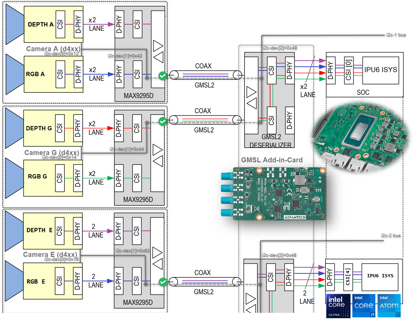
It is crucial to understand the SerDes i2c connectivity specific to each ODM/OEM motherboards, Add-in-Cards (AIC) and GMSL2 Camera modules. Illustrated below are all details a user need to learn about I2C communication between a BDF (Bit-Definition File) Linux i2c adapter and GMSL2 i2c devices for the Intel® Core™ Ultra Series 1 and 2 (Arrow Lake-U/H) and 12th/13th/14th Gen Intel® Core™ to detect and configure GMSL capability. (see SerDes i2c mapping for further details)
A GMSL product design based Intel® Core™ Ultra Series 1 and 2 (Arrow Lake-U/H) or 12th/13th/14th Gen Intel® Core™ products can be illustrated as followed :
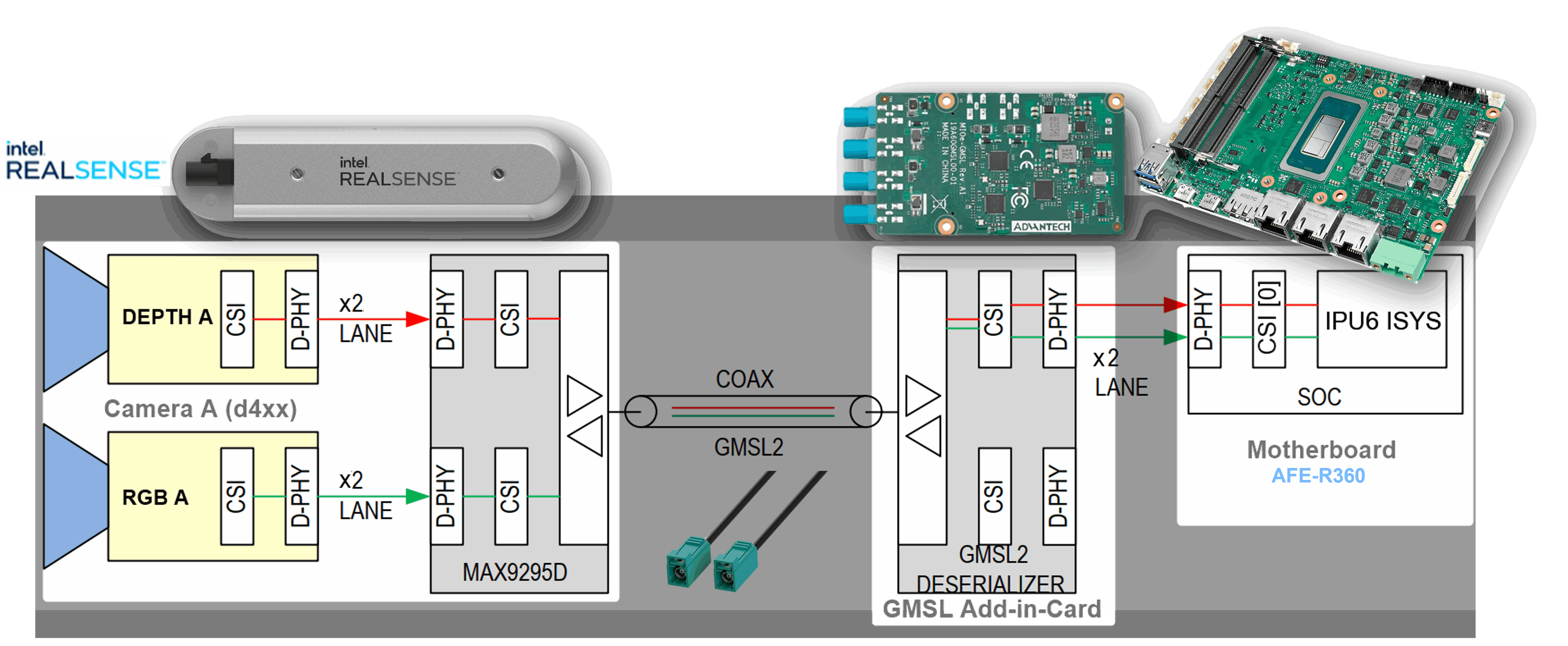
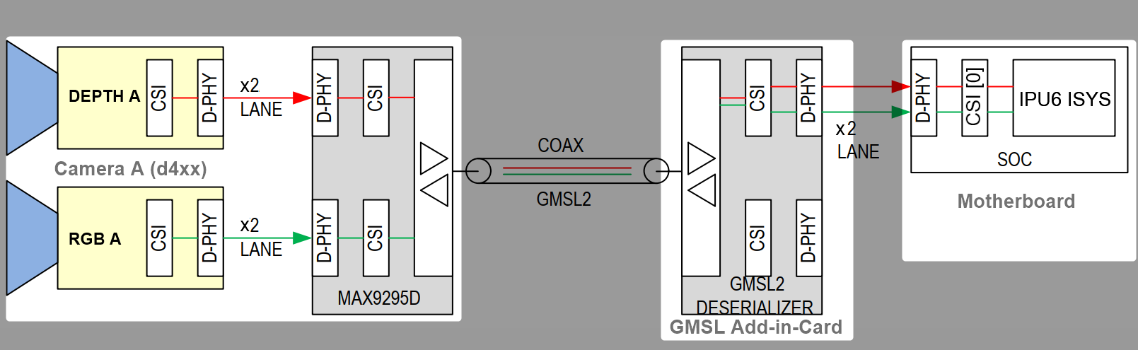
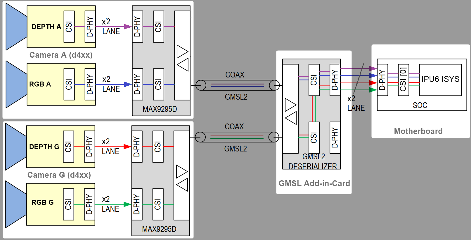
The GMSL2 Camera modules, designed by 3rd Party GMSL2 Camera vendors, combine a Camera Sensor and GMSL2 Serializer (ex. MAX9295)
The Add-in-Card (AIC), designed by either ODM/OEMs or 3rd Party GMSL2 Camera vendors, provide multiple GMSL2 Derializer (ex. MAX9296A)
The |Intel|-based Motherboad, designed by ODM/OEMs, provide Mobile Industry Processor Interface (MIPI) Camera Serial Interface (CSI) interface exposed by Intel® Core™ Ultra Series 1 and 2 (Arrow Lake-U/H) and 12th/13th/14th Gen Intel® Core™ products.
There are two design approaches for GMSL Add-in-Card (AIC) :
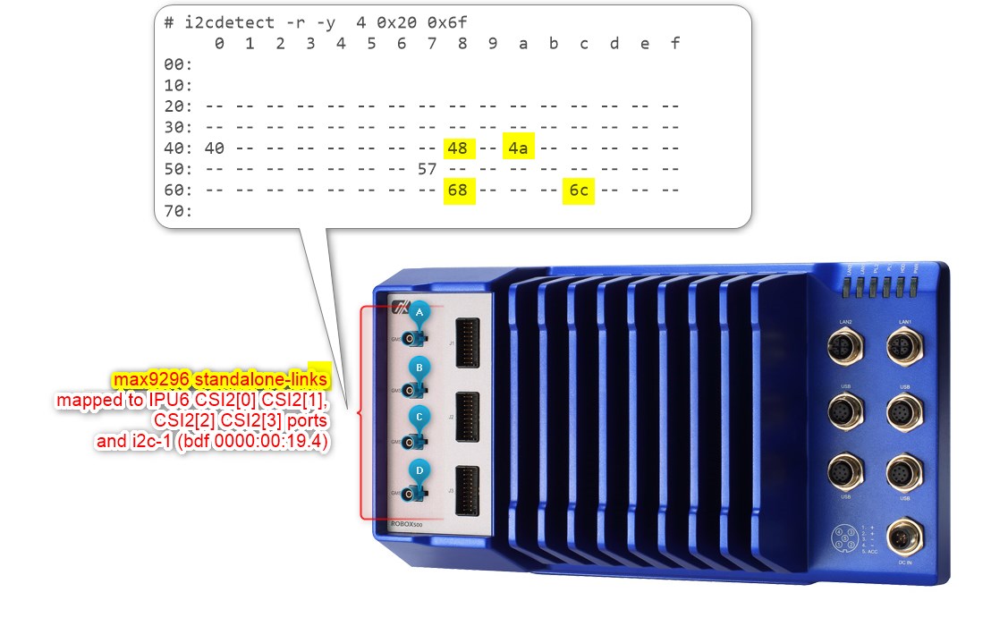
Standalone-mode SerDes - Single GMSL Serializer (ex. MAX9295) and Camera Sensor devices per Deserializer (e.g. MAX9296A). Such as Axiomtek ROBOX500 4x GMSL camera interfaces Add-in-Card (AIC).
It is crucial to understand the SerDes i2c connectivity specific to each ODM/OEM motherboards, Add-in-Cards (AIC) and GMSL2 Camera modules. Illustrated below are all details a user need to learn about I2C communication between a BDF (Bit-Definition File) Linux i2c adapter and GMSL2 i2c devices for the Intel® Core™ Ultra Series 1 and 2 (Arrow Lake-U/H) and 12th/13th/14th Gen Intel® Core™ to detect and configure GMSL capability. (see SerDes i2c mapping for further details)
HOW TO detect in i2c bus to GMSL2 Deserializer and Serializer ACPI devices mapping#
The best way to detect i2c bus to GMSL2 Deserializer and Serializer ACPI devices mapping is by using i2cdetect command line tool from i2c-tools package on Linux OS.
i2cdetect-y<i2c_bus_number>
where <i2c_bus_number> is the i2c bus number assigned to GMSL2 Deserializer and Serializer ACPI devices.
here is an example output of i2cdetect command line tool for GMSL2 Deserializer and Serializer ACPI devices mapping:
As you can see my devices are on ITC i2c bus 0 with address 0x1a, 0x27, 0x40 and 0x54, which are corresponding to GMSL2 Deserializer and Serializer ACPI devices configured on my system.
Select max929x or max967xx deserializer to compile certain linux v4l2 i2c sensors driver with.
Reboot the system and enter into the BIOS/UEFI settings. Navigate to the ACPI configuration section and verify that the GMSL SerDes device is listed and enabled. If it is not present, you may need to update your system firmware or consult your hardware vendor for support.
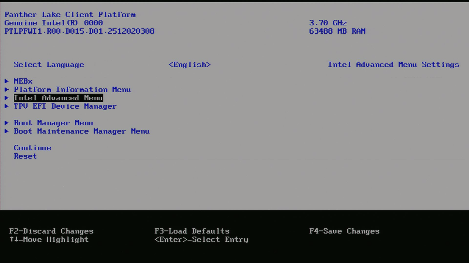
Go into UEFI Advanced setting.
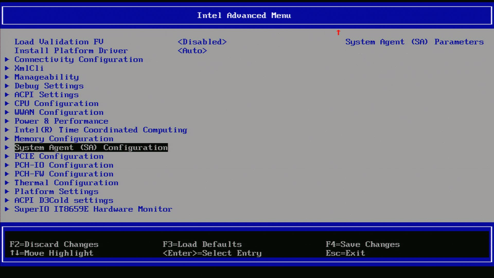
Navigate to System Agent (SA)
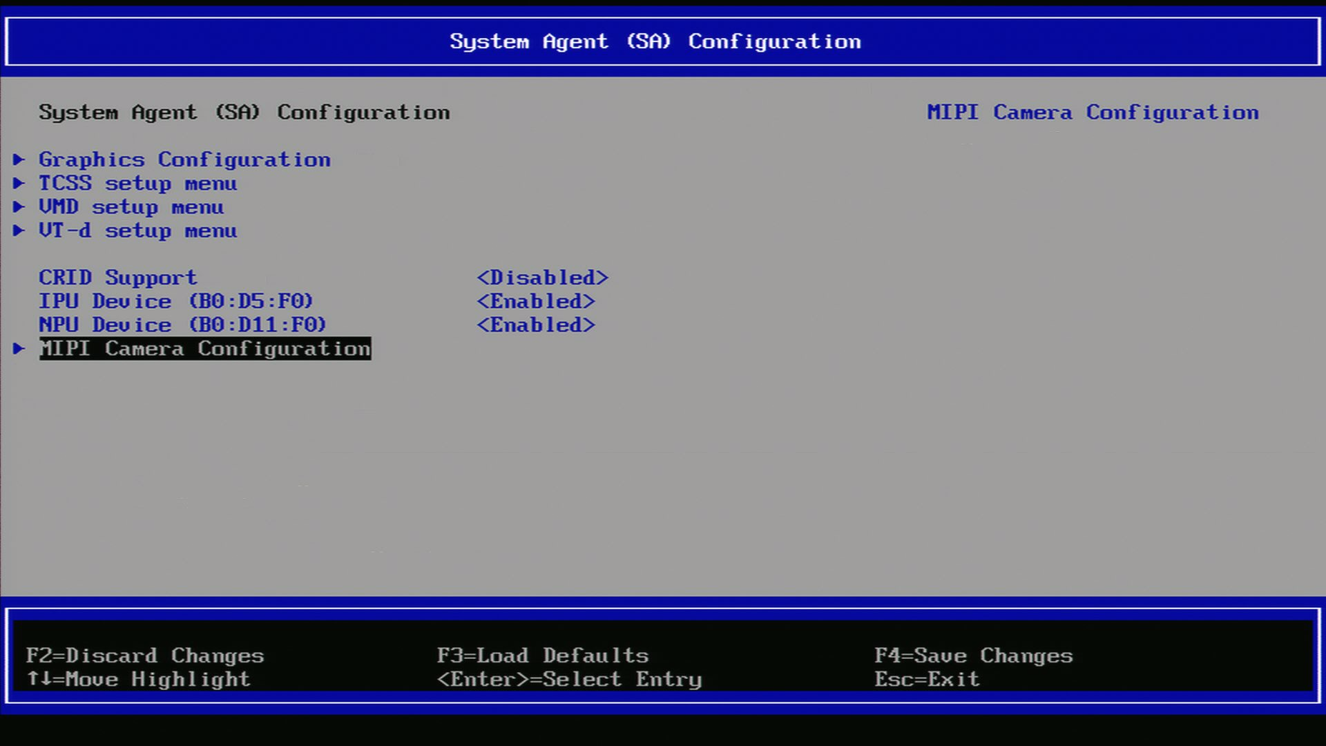
Navigate to MIPI Configuration
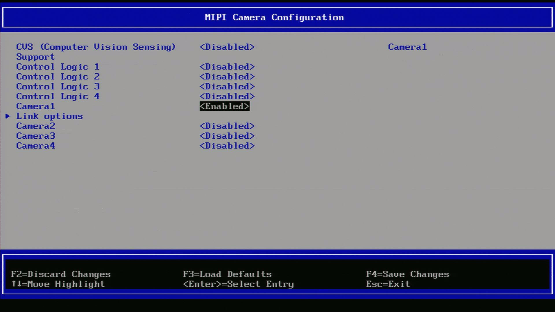
Ensure GMSL SerDes is enabled.
After enabling the GMSL SerDes device in the UEFI settings, click on ‘link options’ to adjust the settings for the GMSL SerDes link.
Below an ACPI devices configure example for GMSL2 Intel® RealSense™ Depth Camera D457 :
Aggregated-link SerDes CSI-2 port 0 and 4 and I2C settings for GMSL Add-in-Card (AIC)#
UEFI Custom Sensor
Camera 1
Camera 2
Camera 3
Camera 4
GMSL Camera suffix
a
g
e
k
Custom HID
INTC10CD
INTC10CD
INTC10CD
INTC10CD
PPR Value
2
2
2
2
PPR Unit
1
1
1
1
Camera module label
d4xx
d4xx
d4xx
d4xx
MIPI Port (Index)
0
0
4
4
LaneUsed
x2
x2
x2
x2
Number of I2C
3
3
3
3
I2C Channel
I2C1
I2C1
I2C2
I2C2
Device0 I2C Address
12
14
12
14
Device1 I2C Address
42
44
42
44
Device2 I2C Address
48
48
48
48
Below an ACPI devices configure example for D3 Embedded Discovery GMSL2 Camera module :
Aggregated-link SerDes CSI-2 port 0 and 4 and I2C settings for GMSL Add-in-Card (AIC)#
UEFI Custom Sensor
Camera 1
Camera 2
GMSL Camera suffix
a
e
Custom HID
D3000004
D3000004
PPR Value
2
2
PPR Unit
2
2
Camera module label
D3CMCXXX-115-084
D3CMCXXX-115-084
MIPI Port (Index)
0
4
LaneUsed
x2
x2
Number of I2C
3
3
I2C Channel
I2C1
I2C2
Device0 I2C Address
48
48
Device1 I2C Address
42
44
Device2 I2C Address
10
12
Attention
please note, on Advantech® AFE-R360 series the four D3CMCXXX ACPI configuration achieved by PPRUnit=2 also requires setting Device0 for GMSL2 Aggregated-link Deserializer I2C address (e.g. MAX9296A) and Device2 for Sensors I2C address (e.g. ISX031).
Aggregated-link SerDes CSI-2 port 0 and 4 and I2C settings for GMSL Add-in-Card (AIC)#
UEFI Custom Sensor
Camera 1
Camera 2
GMSL Camera suffix
a
e
Custom HID
D3000005
D3000005
PPR Value
2
2
PPR Unit
2
2
Camera module label
D3CMCXXX-106-084
D3CMCXXX-106-084
MIPI Port (Index)
0
4
LaneUsed
x2
x2
Number of I2C
3
3
I2C Channel
I2C1
I2C2
Device0 I2C Address
48
48
Device1 I2C Address
42
44
Device2 I2C Address
10
12
Attention
please note, on Advantech® AFE-R360 series the four D3CMCXXX ACPI configuration achieved by PPRUnit=2 also requires setting Device0 for GMSL2 Aggregated-link Deserializer I2C address (e.g. MAX9296A) and Device2 for Sensors I2C address (e.g. ISX031).
Below an ACPI devices configure example for oToBrite® oToCAM222 GMSL2 camera modules :
Aggregated-link SerDes CSI-2 port 0 and 4 and I2C settings for GMSL Add-in-Card (AIC)#
UEFI Custom Sensor
Camera 1
Camera 2
Camera 3
Camera 4
GMSL Camera suffix
a
g
e
k
Custom HID
OTOC1021
OTOC1021
OTOC1021
OTOC1021
PPR Value
2
2
2
2
PPR Unit
1
1
1
1
Camera module label
otocam
otocam
otocam
otocam
MIPI Port (Index)
0
0
4
4
LaneUsed
x2
x2
x2
x2
Number of I2C
3
3
3
3
I2C Channel
I2C1
I2C1
I2C2
I2C2
Device0 I2C Address
10
11
10
11
Device1 I2C Address
18
19
18
19
Device2 I2C Address
48
48
48
48
Below an ACPI devices configure example for oToBrite® oToCAM223 GMSL2 camera modules :
Aggregated-link SerDes CSI-2 port 0 and 4 and I2C settings for GMSL Add-in-Card (AIC)#
UEFI Custom Sensor
Camera 1
Camera 2
Camera 3
Camera 4
GMSL Camera suffix
a
g
e
k
Custom HID
OTOC1031
OTOC1031
OTOC1031
OTOC1031
PPR Value
2
2
2
2
PPR Unit
1
1
1
1
Camera module label
otocam
otocam
otocam
otocam
MIPI Port (Index)
0
0
4
4
LaneUsed
x2
x2
x2
x2
Number of I2C
3
3
3
3
I2C Channel
I2C1
I2C1
I2C2
I2C2
Device0 I2C Address
10
11
10
11
Device1 I2C Address
18
19
18
19
Device2 I2C Address
48
48
48
48
Another example below illustrates how to configure ACPI devices 6x Intel® RealSense™ Depth Camera D457 GMSL2 module :
Aggregated-link SerDes CSI-2 port 0, 4 and 5 and I2C settings for GMSL Add-in-Card (AIC)#
UEFI Custom Sensor
Camera 1
Camera 2
Camera 3
Camera 4
Camera 5 or N/A 1
Camera 6 or N/A 1
GMSL Camera suffix
a
g
e
f
k
l
Custom HID
INTC10CD
INTC10CD
INTC10CD
INTC10CD
INTC10CD
INTC10CD
PPR Value
2
2
2
2
2
2
PPR Unit
1
1
1
1
1
1
Camera module label
d4xx
d4xx
d4xx
d4xx
d4xx
d4xx
MIPI Port (Index)
0
0
4
5
4
5
LaneUsed
x2
x2
x2
x2
x2
x2
Number of I2C
3
3
3
3
3
3
I2C Channel
I2C1
I2C1
I2C2
I2C2
I2C2
I2C2
Device0 I2C Address
12
14
16
18
12
14
Device1 I2C Address
42
44
62
42
64
44
Device2 I2C Address
48
48
48
4a
48
4a
Attention
For the time being each GMSL2 Aggregated-link Deserializer (e.g. MAX9296A) on the same I2C Channel shall set identical Custom HID and Camera module label tuple matching with GMSL2 Serializer and Camera Sensor devices type.
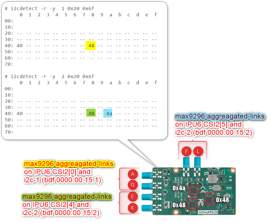
The Advantech GMSL Input Module Card for AFE-R360 series I2C1 Channel (ex. INTC10CD) Aggregated-link Deserializer (e.g. MAX9296A) i2c device 0x48 shall set Custom HID (ex. INTC10CD) and Camera module label (ex d4xx) tuple for both GMSL Camera suffix a and g, where the other Aggregated-link Deserializer (e.g. MAX9296A) i2c device 0x4a could have a different Custom HID (ex INTC1031) and Camera module label (ex isx031) tuple on both GMSL Camera suffix e and k.
The SEAVO® Embedded Computer HB03 UEFI BIOS Version:S1132C1133A11 allow admin user to configure up to 4x GMSL2 camera interface (FAKRA universal type).
Below an ACPI devices configure example for GMSL2 Intel® RealSense™ Depth Camera D457 :
Aggregated-link SerDes CSI-2 port 0 and 4 and I2C settings for GMSL Add-in-Card (AIC)#
UEFI Custom Sensor
Camera 1
Camera 2
Camera 3
Camera 4
GMSL Camera suffix
a
g
e
k
Custom HID
INTC10CD
INTC10CD
INTC10CD
INTC10CD
PPR Value
2
2
2
2
PPR Unit
1
1
1
1
Camera module label
d4xx
d4xx
d4xx
d4xx
MIPI Port (Index)
0
0
4
4
LaneUsed
x4
x4
x4
x4
Number of I2C
3
3
3
3
I2C Channel
I2C1
I2C1
I2C0
I2C0
Device0 I2C Address
12
14
12
14
Device1 I2C Address
42
44
42
44
Device2 I2C Address
48
48
48
48
Below an ACPI devices configure example for D3 Embedded Discovery GMSL2 Camera module :
Aggregated-link SerDes CSI-2 port 0 and 4 and I2C settings for GMSL Add-in-Card (AIC)#
UEFI Custom Sensor
Camera 1
Camera 2
GMSL Camera suffix
a
e
Custom HID
D3000004
D3000004
PPR Value
2
2
PPR Unit
2
2
Camera module label
D3CMCXXX-115-084
D3CMCXXX-115-084
MIPI Port (Index)
0
4
LaneUsed
x4
x4
Number of I2C
3
3
I2C Channel
I2C1
I2C0
Device0 I2C Address
48
48
Device1 I2C Address
42
44
Device2 I2C Address
10
12
Attention
please note, on Seavo® HB03 the four D3CMCXXX ACPI configuration achieved by PPRUnit=2 also requires setting Device0 for GMSL2 Aggregated-link Deserializer I2C address (e.g. MAX9296A) and Device2 for Sensors I2C address (e.g. ISX031).
Aggregated-link SerDes CSI-2 port 0 and 4 and I2C settings for GMSL Add-in-Card (AIC)#
UEFI Custom Sensor
Camera 1
Camera 2
GMSL Camera suffix
a
e
Custom HID
D3000005
D3000005
PPR Value
2
2
PPR Unit
2
2
Camera module label
D3CMCXXX-106-084
D3CMCXXX-106-084
MIPI Port (Index)
0
4
LaneUsed
x4
x4
Number of I2C
3
3
I2C Channel
I2C1
I2C0
Device0 I2C Address
48
48
Device1 I2C Address
42
44
Device2 I2C Address
10
12
Attention
please note, on Seavo® HB03 four D3CMCXXX ACPI configuration achieved by PPRUnit=2 also requires setting Device0 for GMSL2 Aggregated-link Deserializer I2C address (e.g. MAX9296A) and Device2 for Sensors I2C address (e.g. ISX031).
Below an ACPI devices configure example for oToBrite® oToCAM222 GMSL2 camera modules :
Aggregated-link SerDes CSI-2 port 0 and 4 and I2C settings for GMSL Add-in-Card (AIC)#
UEFI Custom Sensor
Camera 1
Camera 2
Camera 3
Camera 4
GMSL Camera suffix
a
g
e
k
Custom HID
OTOC1021
OTOC1021
OTOC1021
OTOC1021
PPR Value
2
2
2
2
PPR Unit
1
1
1
1
Camera module label
otocam
otocam
otocam
otocam
MIPI Port (Index)
0
0
4
4
LaneUsed
x4
x4
x4
x4
Number of I2C
3
3
3
3
I2C Channel
I2C1
I2C1
I2C0
I2C0
Device0 I2C Address
10
11
10
11
Device1 I2C Address
18
19
18
19
Device2 I2C Address
48
48
48
48
Below an ACPI devices configure example for oToBrite® oToCAM223 GMSL2 camera modules :
Aggregated-link SerDes CSI-2 port 0 and 4 and I2C settings for GMSL Add-in-Card (AIC)#
UEFI Custom Sensor
Camera 1
Camera 2
Camera 3
Camera 4
GMSL Camera suffix
a
g
e
k
Custom HID
OTOC1031
OTOC1031
OTOC1031
OTOC1031
PPR Value
2
2
2
2
PPR Unit
1
1
1
1
Camera module label
otocam
otocam
otocam
otocam
MIPI Port (Index)
0
0
4
4
LaneUsed
x4
x4
x4
x4
Number of I2C
3
3
3
3
I2C Channel
I2C1
I2C1
I2C0
I2C0
Device0 I2C Address
10
11
10
11
Device1 I2C Address
18
19
18
19
Device2 I2C Address
48
48
48
48
Note
please note, GMSL2 Aggregated-link SerDes CSI-2 port 0 and 4 is purposely set to LaneUsed=x4 to improve Intel® IPU6 DPHY signal-integrity problem on SEAVO® Embedded Computer HB03 .
Attention
For the time being each GMSL2 Aggregated-link Deserializer (e.g. MAX9296A) on the same I2C Channel shall set identical Custom HID and Camera module label tuple matching with GMSL2 Serializer and Camera Sensor devices type.
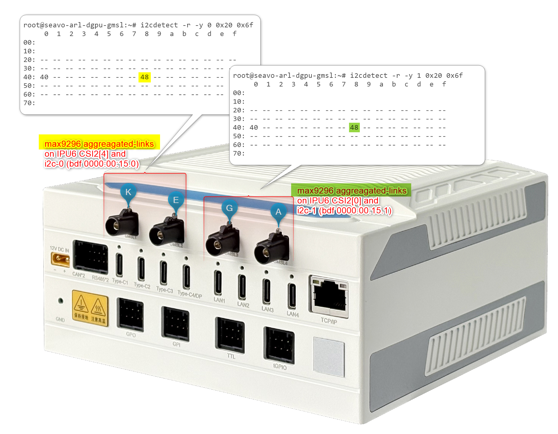
The SEAVO® Embedded Computer HB03 Add-in-Cards (AIC) I2C1 Channel (ex. INTC10CD) Aggregated-link Deserializer (e.g. MAX9296A) i2c device 0x48 shall set Custom HID (ex. INTC10CD) and Camera module label (ex d4xx) tuple for both GMSL Camera suffix a and g, where the other Aggregated-link Deserializer (e.g. MAX9296A) i2c device 0x4a could have a different Custom HID (ex INTC1031) and Camera module label (ex isx031) tuple on both GMSL Camera suffix e and k.
The Axiomtek ROBOX500 may provide either 4x GMSL or 8x GMSL camera interface (FAKRA universal type).
Below an ACPI devices configure example for 4x Intel® RealSense™ Depth Camera D457 GMSL2 module :
Standalone-link SerDes CSI-2 port 0, 1, 2 and 3 and I2C settings for GMSL Add-in-Card (AIC)#
UEFI Custom Sensor
Camera 1
Camera 2
Camera 3
Camera 4
Camera suffix
a
b
c
d
Custom HID
INTC10CD
INTC10CD
INTC10CD
INTC10CD
PPR Value
2
2
2
2
PPR Unit
1
1
1
1
Camera module label
d4xx
d4xx
d4xx
d4xx
MIPI Port (Index)
0
1
2
3
LaneUsed
x2
x2
x2
x2
Number of I2C
3
3
3
3
I2C Channel
I2C5
I2C5
I2C5
I2C5
Device0 I2C Address
12
14
16
18
Device1 I2C Address
42
44
62
64
Device2 I2C Address
48
4a
68
6c
Below an ACPI devices configure example of four GMSL2 Camera module from D3 Embedded Discovery:
Aggregated-link SerDes CSI-2 port 0 and 4 and I2C settings for GMSL Add-in-Card (AIC)#
UEFI Custom Sensor
Camera 1
Camera 2
Camera 3
Camera 4
Camera suffix
a
b
c
d
Custom HID
D3000004
D3000004
D3000004
D3000004
PPR Value
2
2
2
2
PPR Unit
1
1
1
1
Camera module label
D3CMCXXX-115-084
D3CMCXXX-115-084
D3CMCXXX-115-084
D3CMCXXX-115-084
MIPI Port (Index)
0
1
2
3
LaneUsed
x2
x2
x2
x2
Number of I2C
3
3
3
3
I2C Channel
I2C5
I2C5
I2C5
I2C5
Device0 I2C Address
48
4a
68
6c
Device1 I2C Address
42
44
62
64
Device2 I2C Address
12
14
16
18
Attention
please note, on the Axiomtek® ROBOX500 the 4x D3CMCXXX Camera ACPI configuration is achieved by PPRUnit=1 requires setting Device0 for GMSL2 Aggregated-link Deserializer I2C address (e.g. MAX9296A) and Device2 for Sensors I2C address (e.g. ISX031).
Below an ACPI devices configure example of four GMSL2 Camera module from D3 Embedded Discovery PRO :
Aggregated-link SerDes CSI-2 port 0 and 4 and I2C settings for GMSL Add-in-Card (AIC)#
UEFI Custom Sensor
Camera 1
Camera 2
Camera 3
Camera 4
Camera suffix
a
b
c
d
Custom HID
D3000005
D3000005
D3000005
D3000005
PPR Value
2
2
2
2
PPR Unit
1
1
1
1
Camera module label
D3CMCXXX-106-084
D3CMCXXX-106-084
D3CMCXXX-106-084
D3CMCXXX-106-084
MIPI Port (Index)
0
1
2
3
LaneUsed
x2
x2
x2
x2
Number of I2C
3
3
3
3
I2C Channel
I2C5
I2C5
I2C5
I2C5
Device0 I2C Address
48
4a
68
6c
Device1 I2C Address
42
44
62
64
Device2 I2C Address
12
14
16
18
Attention
please note, the D3CMCXXX ACPI configuration with PPRUnit=2 requires setting Device0 for GMSL2 Aggregated-link Deserializer I2C address (e.g. MAX9296A) and Device2 for Sensors I2C address (e.g. ISX031).
Below an ACPI devices configure example for oToBrite® oToCAM222 GMSL2 camera modules :
Aggregated-link SerDes CSI-2 port 0 and 4 and I2C settings for GMSL Add-in-Card (AIC)#
UEFI Custom Sensor
Camera 1
Camera 2
Camera 3
Camera 4
GMSL Camera suffix
a
b
c
d
Custom HID
OTOC1021
OTOC1021
OTOC1021
OTOC1021
PPR Value
2
2
2
2
PPR Unit
1
1
1
1
Camera module label
otocam
otocam
otocam
otocam
MIPI Port (Index)
0
1
2
3
LaneUsed
x2
x2
x2
x2
Number of I2C
3
3
3
3
I2C Channel
I2C5
I2C5
I2C5
I2C5
Device0 I2C Address
10
11
10
11
Device1 I2C Address
18
19
18
19
Device2 I2C Address
48
4a
68
6c
Below an ACPI devices configure example for oToBrite® oToCAM223 GMSL2 camera modules :
Aggregated-link SerDes CSI-2 port 0 and 4 and I2C settings for GMSL Add-in-Card (AIC)#
UEFI Custom Sensor
Camera 1
Camera 2
Camera 3
Camera 4
GMSL Camera suffix
a
b
c
d
Custom HID
OTOC1031
OTOC1031
OTOC1031
OTOC1031
PPR Value
2
2
2
2
PPR Unit
1
1
1
1
Camera module label
otocam
otocam
otocam
otocam
MIPI Port (Index)
0
1
2
3
LaneUsed
x2
x2
x2
x2
Number of I2C
3
3
3
3
I2C Channel
I2C5
I2C5
I2C5
I2C5
Device0 I2C Address
10
11
10
11
Device1 I2C Address
18
19
18
19
Device2 I2C Address
48
4a
68
6c
Another example below illustrates how to configure ACPI devices 8x Intel® RealSense™ Depth Camera D457 GMSL2 module :
Aggregated-link SerDes CSI-2 port 0, 1, 2 and 3 and I2C settings for GMSL Add-in-Card (AIC)#