Configure Intel® GMSL SerDes ACPI Devices#
To enable multiple GMSL cameras, for the same or different vendors, define the MIPI camera ACPI device in UEFI/BIOS settings.
Review Intel®-enabled GMSL2 camera modules with their corresponding ACPI device custom HIDs:
ACPI custom HID
Camera module label
Sensor type
GMSL2 serializer
Max resolution
Vendor URL
INTC10CDd4xxOV9782 + D450 Depth
MAX9295
2x (1280x720)
D3000004D3CMCXXX-115-084ISX031
MAX9295
1920x1536
D3000005D3CMCXXX-106-084IMX390
MAX9295
1920x1080
sensor Linux drivers package available upon
sales@d3embedded.comcamera purchaseD3000006D3CMCXXX-089-084AR0234
MAX9295
1280x960
OTOC1031otocamISX031
MAX9295
1920x1536
OTOC1021otocamISX021
MAX9295
1920x1280
sensor Linux drivers package available upon
sales@otobrite.comcamera purchaseReview the GMSL Add-in-Card Design Overview, if not already done.
Refer to each tab below to understand the distinct ACPI camera device configuration tables for ODM hardware.
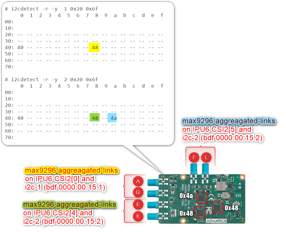
The Advantech® GMSL Input Module Card for AFE-R360 series and ASR-A502 series may provide up to 6x GMSL camera interfaces (FAKRA universal type).
Below is an ACPI device configuration example for the GMSL2 RealSense Depth Camera D457:
Aggregated-link
SerDesCSI-2 port 0 and 4 and I2C settings for GMSL Add-in-Card (AIC)UEFI Custom Sensor
Camera 1
Camera 2
Camera 3
Camera 4
GMSL Camera suffix
a
g
e
k
Custom HID
INTC10CDINTC10CDINTC10CDINTC10CDPPR Value
2
2
2
2
PPR Unit
1
1
1
1
Camera module label
d4xxd4xxd4xxd4xxMIPI Port (Index)
0
0
4
4
LaneUsed
x2
x2
x2
x2
Number of I2C
3
3
3
3
I2C Channel
I2C1
I2C1
I2C2
I2C2
Device0 I2C Address
12
14
12
14
Device1 I2C Address
42
44
42
44
Device2 I2C Address
48
48
48
48
Below is an ACPI device configuration example for the D3 Embedded Discovery GMSL2 camera module:
Aggregated-link
SerDesCSI-2 port 0 and 4 and I2C settings for GMSL Add-in-Card (AIC)UEFI Custom Sensor
Camera 1
Camera 2
GMSL Camera suffix
a
e
Custom HID
D3000004D3000004PPR Value
2
2
PPR Unit
2
2
Camera module label
D3CMCXXX-115-084D3CMCXXX-115-084MIPI Port (Index)
0
4
LaneUsed
x2
x2
Number of I2C
3
3
I2C Channel
I2C1
I2C2
Device0 I2C Address
48
48
Device1 I2C Address
42
44
Device2 I2C Address
10
12
Note: on Advantech® AFE-R360 series the four D3CMCXXX ACPI configurations achieved by
PPR Unit=2also require settingDevice0for the GMSL2 aggregated-link deserializer I2C address, for exampleMAX9296A, andDevice2for the sensor I2C address, for exampleISX031.Below is an ACPI device configuration example for the D3 Embedded Discovery PRO GMSL2 camera module:
Aggregated-link
SerDesCSI-2 port 0 and 4 and I2C settings for GMSL Add-in-Card (AIC)UEFI Custom Sensor
Camera 1
Camera 2
GMSL Camera suffix
a
e
Custom HID
D3000005D3000005PPR Value
2
2
PPR Unit
2
2
Camera module label
D3CMCXXX-106-084D3CMCXXX-106-084MIPI Port (Index)
0
4
LaneUsed
x2
x2
Number of I2C
3
3
I2C Channel
I2C1
I2C2
Device0 I2C Address
48
48
Device1 I2C Address
42
44
Device2 I2C Address
10
12
Note: on Advantech® AFE-R360 series the four D3CMCXXX ACPI configurations achieved by
PPR Unit=2also require settingDevice0for the GMSL2 aggregated-link deserializer I2C address, for exampleMAX9296A, andDevice2for the sensor I2C address, for exampleISX031.Below is an ACPI device configuration example for oToBrite oToCAM222 GMSL2 camera modules:
Aggregated-link
SerDesCSI-2 port 0 and 4 and I2C settings for GMSL Add-in-Card (AIC)UEFI Custom Sensor
Camera 1
Camera 2
Camera 3
Camera 4
GMSL Camera suffix
a
g
e
k
Custom HID
OTOC1021OTOC1021OTOC1021OTOC1021PPR Value
2
2
2
2
PPR Unit
1
1
1
1
Camera module label
otocamotocamotocamotocamMIPI Port (Index)
0
0
4
4
LaneUsed
x2
x2
x2
x2
Number of I2C
3
3
3
3
I2C Channel
I2C1
I2C1
I2C2
I2C2
Device0 I2C Address
10
11
10
11
Device1 I2C Address
18
19
18
19
Device2 I2C Address
48
48
48
48
Below is an ACPI device configuration example for oToBrite oToCAM223 GMSL2 camera modules:
Aggregated-link
SerDesCSI-2 port 0 and 4 and I2C settings for GMSL Add-in-Card (AIC)UEFI Custom Sensor
Camera 1
Camera 2
Camera 3
Camera 4
GMSL Camera suffix
a
g
e
k
Custom HID
OTOC1031OTOC1031OTOC1031OTOC1031PPR Value
2
2
2
2
PPR Unit
1
1
1
1
Camera module label
otocamotocamotocamotocamMIPI Port (Index)
0
0
4
4
LaneUsed
x2
x2
x2
x2
Number of I2C
3
3
3
3
I2C Channel
I2C1
I2C1
I2C2
I2C2
Device0 I2C Address
10
11
10
11
Device1 I2C Address
18
19
18
19
Device2 I2C Address
48
48
48
48
Another example below illustrates how to configure ACPI devices for 6x RealSense Depth Camera D457 GMSL2 modules:
Aggregated-link
SerDesCSI-2 port 0, 4 and 5 and I2C settings for GMSL Add-in-Card (AIC)UEFI Custom Sensor
Camera 1
Camera 2
Camera 3
Camera 4
Camera 5 or N/A
Camera 6 or N/A
GMSL Camera suffix
a
g
e
f
k
l
Custom HID
INTC10CDINTC10CDINTC10CDINTC10CDINTC10CDINTC10CDPPR Value
2
2
2
2
2
2
PPR Unit
1
1
1
1
1
1
Camera module label
d4xxd4xxd4xxd4xxd4xxd4xxMIPI Port (Index)
0
0
4
5
4
5
LaneUsed
x2
x2
x2
x2
x2
x2
Number of I2C
3
3
3
3
3
3
I2C Channel
I2C1
I2C1
I2C2
I2C2
I2C2
I2C2
Device0 I2C Address
12
14
16
18
12
14
Device1 I2C Address
42
44
62
42
64
44
Device2 I2C Address
48
48
48
4a
48
4a
Attention: For the time being, each GMSL2 aggregated-link deserializer, for example
MAX9296A, on the same I2C channel must set an identical Custom HID and Camera module label tuple matching the GMSL2 serializer and camera sensor device type.For the Advantech® GMSL Input Module Card for AFE-R360 series, the I2C1-channel aggregated-link deserializer at I2C device
0x48can set the Custom HID, for exampleINTC10CD, and Camera module label, for exampled4xx, tuple for both GMSL camera suffixesaandg, while the other aggregated-link deserializer at I2C device0x4acan use a different Custom HID, for exampleINTC1031, and Camera module label, for exampleisx031, tuple on GMSL camera suffixeseandk.The SEAVO® Embedded Computer HB03 UEFI BIOS
Version: S1132C1133A11allows an admin user to configure up to 4x GMSL2 camera interfaces (FAKRA universal type).Below is an ACPI device configuration example for the GMSL2 RealSense Depth Camera D457:
Aggregated-link
SerDesCSI-2 port 0 and 4 and I2C settings for GMSL Add-in-Card (AIC)UEFI Custom Sensor
Camera 1
Camera 2
Camera 3
Camera 4
GMSL Camera suffix
a
g
e
k
Custom HID
INTC10CDINTC10CDINTC10CDINTC10CDPPR Value
2
2
2
2
PPR Unit
1
1
1
1
Camera module label
d4xxd4xxd4xxd4xxMIPI Port (Index)
0
0
4
4
LaneUsed
x4
x4
x4
x4
Number of I2C
3
3
3
3
I2C Channel
I2C1
I2C1
I2C0
I2C0
Device0 I2C Address
12
14
12
14
Device1 I2C Address
42
44
42
44
Device2 I2C Address
48
48
48
48
Below is an ACPI device configuration example for the D3 Embedded Discovery GMSL2 camera module:
Aggregated-link
SerDesCSI-2 port 0 and 4 and I2C settings for GMSL Add-in-Card (AIC)UEFI Custom Sensor
Camera 1
Camera 2
GMSL Camera suffix
a
e
Custom HID
D3000004D3000004PPR Value
2
2
PPR Unit
2
2
Camera module label
D3CMCXXX-115-084D3CMCXXX-115-084MIPI Port (Index)
0
4
LaneUsed
x4
x4
Number of I2C
3
3
I2C Channel
I2C1
I2C0
Device0 I2C Address
48
48
Device1 I2C Address
42
44
Device2 I2C Address
10
12
Note: On SEAVO® HB03, the four D3CMCXXX ACPI configurations achieved by
PPR Unit=2also require settingDevice0for the GMSL2 aggregated-link deserializer I2C address, for exampleMAX9296A, andDevice2for the sensor I2C address, for exampleISX031.Below is an ACPI device configuration example for the D3 Embedded Discovery PRO GMSL2 camera module:
Aggregated-link
SerDesCSI-2 port 0 and 4 and I2C settings for GMSL Add-in-Card (AIC)UEFI Custom Sensor
Camera 1
Camera 2
GMSL Camera suffix
a
e
Custom HID
D3000005D3000005PPR Value
2
2
PPR Unit
2
2
Camera module label
D3CMCXXX-106-084D3CMCXXX-106-084MIPI Port (Index)
0
4
LaneUsed
x4
x4
Number of I2C
3
3
I2C Channel
I2C1
I2C0
Device0 I2C Address
48
48
Device1 I2C Address
42
44
Device2 I2C Address
10
12
Note: On SEAVO® HB03, the four D3CMCXXX ACPI configurations achieved by
PPR Unit=2also require settingDevice0for the GMSL2 aggregated-link deserializer I2C address, for exampleMAX9296A, andDevice2for the sensor I2C address, for exampleISX031.Below is an ACPI device configuration example for oToBrite oToCAM222 GMSL2 camera modules:
Aggregated-link
SerDesCSI-2 port 0 and 4 and I2C settings for GMSL Add-in-Card (AIC)UEFI Custom Sensor
Camera 1
Camera 2
Camera 3
Camera 4
GMSL Camera suffix
a
g
e
k
Custom HID
OTOC1021OTOC1021OTOC1021OTOC1021PPR Value
2
2
2
2
PPR Unit
1
1
1
1
Camera module label
otocamotocamotocamotocamMIPI Port (Index)
0
0
4
4
LaneUsed
x4
x4
x4
x4
Number of I2C
3
3
3
3
I2C Channel
I2C1
I2C1
I2C0
I2C0
Device0 I2C Address
10
11
10
11
Device1 I2C Address
18
19
18
19
Device2 I2C Address
48
48
48
48
Below is an ACPI device configuration example for oToBrite oToCAM223 GMSL2 camera modules:
Aggregated-link
SerDesCSI-2 port 0 and 4 and I2C settings for GMSL Add-in-Card (AIC)UEFI Custom Sensor
Camera 1
Camera 2
Camera 3
Camera 4
GMSL Camera suffix
a
g
e
k
Custom HID
OTOC1031OTOC1031OTOC1031OTOC1031PPR Value
2
2
2
2
PPR Unit
1
1
1
1
Camera module label
otocamotocamotocamotocamMIPI Port (Index)
0
0
4
4
LaneUsed
x4
x4
x4
x4
Number of I2C
3
3
3
3
I2C Channel
I2C1
I2C1
I2C0
I2C0
Device0 I2C Address
10
11
10
11
Device1 I2C Address
18
19
18
19
Device2 I2C Address
48
48
48
48
Note: GMSL2 aggregated-link
SerDesCSI-2 ports 0 and 4 are purposely set toLaneUsed = x4to improve Intel® IPU6 DPHY signal-integrity issues on the SEAVO® Embedded Computer HB03.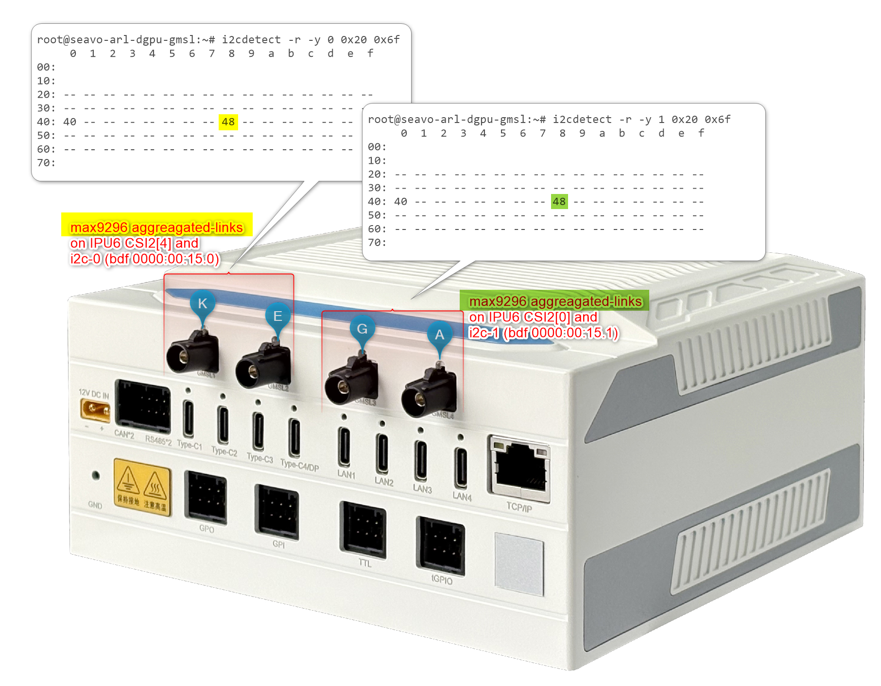
Attention: For the time being, each GMSL2 aggregated-link deserializer, for example
MAX9296A, on the same I2C channel must set an identical Custom HID and Camera module label tuple matching the GMSL2 serializer and camera sensor device type.For the SEAVO® Embedded Computer HB03 Add-in-Card (AIC), the I2C1-channel aggregated-link deserializer at I2C device
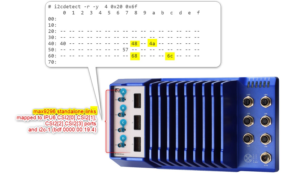
0x48can set the Custom HID, for exampleINTC10CD, and Camera module label, for exampled4xx, tuple for both GMSL camera suffixesaandg, while the other aggregated-link deserializer at I2C device0x4acan use a different Custom HID, for exampleINTC1031, and Camera module label, for exampleisx031, tuple on GMSL camera suffixeseandk.The Axiomtek® ROBOX500 may provide either 4x GMSL or 8x GMSL camera interfaces (FAKRA universal type).
Below is an ACPI device configuration example for 4x RealSense Depth Camera D457 GMSL2 modules:
Standalone-link
SerDesCSI-2 port 0, 1, 2 and 3 and I2C settings for GMSL Add-in-Card (AIC)UEFI Custom Sensor
Camera 1
Camera 2
Camera 3
Camera 4
Camera suffix
a
b
c
d
Custom HID
INTC10CDINTC10CDINTC10CDINTC10CDPPR Value
2
2
2
2
PPR Unit
1
1
1
1
Camera module label
d4xxd4xxd4xxd4xxMIPI Port (Index)
0
1
2
3
LaneUsed
x2
x2
x2
x2
Number of I2C
3
3
3
3
I2C Channel
I2C5
I2C5
I2C5
I2C5
Device0 I2C Address
12
14
16
18
Device1 I2C Address
42
44
62
64
Device2 I2C Address
48
4a
68
6c
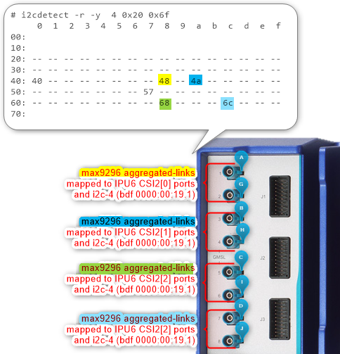
Below is an ACPI device configuration example for four GMSL2 camera modules from D3 Embedded Discovery:
Aggregated-link
SerDesCSI-2 port 0 and 4 and I2C settings for GMSL Add-in-Card (AIC)UEFI Custom Sensor
Camera 1
Camera 2
Camera 3
Camera 4
Camera suffix
a
b
c
d
Custom HID
D3000004D3000004D3000004D3000004PPR Value
2
2
2
2
PPR Unit
1
1
1
1
Camera module label
D3CMCXXX-115-084D3CMCXXX-115-084D3CMCXXX-115-084D3CMCXXX-115-084MIPI Port (Index)
0
1
2
3
LaneUsed
x2
x2
x2
x2
Number of I2C
3
3
3
3
I2C Channel
I2C5
I2C5
I2C5
I2C5
Device0 I2C Address
48
4a
68
6c
Device1 I2C Address
42
44
62
64
Device2 I2C Address
12
14
16
18
Note: On Axiomtek ROBOX500, the 4x D3CMCXXX camera ACPI configuration achieved by
PPR Unit=1requires settingDevice0for the GMSL2 aggregated-link deserializer I2C address, for exampleMAX9296A, andDevice2for the sensor I2C address, for exampleISX031.Below is an ACPI device configuration example for four GMSL2 camera modules from D3 Embedded Discovery PRO:
Aggregated-link
SerDesCSI-2 port 0 and 4 and I2C settings for GMSL Add-in-Card (AIC)UEFI Custom Sensor
Camera 1
Camera 2
Camera 3
Camera 4
Camera suffix
a
b
c
d
Custom HID
D3000005D3000005D3000005D3000005PPR Value
2
2
2
2
PPR Unit
1
1
1
1
Camera module label
D3CMCXXX-106-084D3CMCXXX-106-084D3CMCXXX-106-084D3CMCXXX-106-084MIPI Port (Index)
0
1
2
3
LaneUsed
x2
x2
x2
x2
Number of I2C
3
3
3
3
I2C Channel
I2C5
I2C5
I2C5
I2C5
Device0 I2C Address
48
4a
68
6c
Device1 I2C Address
42
44
62
64
Device2 I2C Address
12
14
16
18
Note: The D3CMCXXX ACPI configuration with
PPR Unit=2requires settingDevice0for the GMSL2 aggregated-link deserializer I2C address, for exampleMAX9296A, andDevice2for the sensor I2C address, for exampleISX031.Below is an ACPI device configuration example for oToBrite oToCAM222 GMSL2 camera modules:
Aggregated-link
SerDesCSI-2 port 0 and 4 and I2C settings for GMSL Add-in-Card (AIC)UEFI Custom Sensor
Camera 1
Camera 2
Camera 3
Camera 4
GMSL Camera suffix
a
b
c
d
Custom HID
OTOC1021OTOC1021OTOC1021OTOC1021PPR Value
2
2
2
2
PPR Unit
1
1
1
1
Camera module label
otocamotocamotocamotocamMIPI Port (Index)
0
1
2
3
LaneUsed
x2
x2
x2
x2
Number of I2C
3
3
3
3
I2C Channel
I2C5
I2C5
I2C5
I2C5
Device0 I2C Address
10
11
10
11
Device1 I2C Address
18
19
18
19
Device2 I2C Address
48
4a
68
6c
Below is an ACPI device configuration example for oToBrite oToCAM223 GMSL2 camera modules:
Aggregated-link
SerDesCSI-2 port 0 and 4 and I2C settings for GMSL Add-in-Card (AIC)UEFI Custom Sensor
Camera 1
Camera 2
Camera 3
Camera 4
GMSL Camera suffix
a
b
c
d
Custom HID
OTOC1031OTOC1031OTOC1031OTOC1031PPR Value
2
2
2
2
PPR Unit
1
1
1
1
Camera module label
otocamotocamotocamotocamMIPI Port (Index)
0
1
2
3
LaneUsed
x2
x2
x2
x2
Number of I2C
3
3
3
3
I2C Channel
I2C5
I2C5
I2C5
I2C5
Device0 I2C Address
10
11
10
11
Device1 I2C Address
18
19
18
19
Device2 I2C Address
48
4a
68
6c
Another example below illustrates how to configure ACPI devices for 8x RealSense Depth Camera D457 GMSL2 modules:
Aggregated-link
SerDesCSI-2 port 0, 1, 2 and 3 and I2C settings for GMSL Add-in-Card (AIC)UEFI Custom Sensor
Camera 1
Camera 2
Camera 3
Camera 4
N/A
N/A
N/A
N/A
Camera suffix (letter)
a
b
c
d
g
h
i
j
Custom HID
INTC10CDINTC10CDINTC10CDINTC10CDINTC10CDINTC10CDINTC10CDINTC10CDPPR Value
2
2
2
2
2
2
2
2
PPR Unit
1
1
1
1
1
1
1
1
Camera module label
d4xxd4xxd4xxd4xxd4xxd4xxd4xxd4xxMIPI Port (Index)
0
1
2
3
0
1
2
3
LaneUsed
x2
x2
x2
x2
x2
x2
x2
x2
Number of I2C
3
3
3
3
3
3
3
3
I2C Channel
I2C5
I2C5
I2C5
I2C5
I2C5
I2C5
I2C5
I2C5
Device0 I2C Address
12
14
16
18
13
15
17
19
Device1 I2C Address
42
44
62
64
43
45
63
65
Device2 I2C Address
48
4a
68
6c
48
4a
68
6c