Stationary Robot Toolkit Vision and Controls Deployment Reference Demo#
The Stationary Robot Toolkit Vision and Controls Reference Demo (RVC) is a ROS 2 Jazzy reference application for vision-guided pick-and-place workflows with a fixed industrial manipulator.
Architecture and Workflow#
The demonstration connects real-time camera perception, 2D/3D grasp selection, state-machine task orchestration, and MoveIt 2 Servo trajectory streaming into an integrated industrial cell pipeline.
        flowchart LR
    camera[RealSense Depth Camera] --> perception[Perception Engine]
    perception --> grasp[Oriented Grasp Selection]
    grasp --> sm[State Machine Node]
    sm --> motion[MoveIt 2 Servo Controller]
    motion --> driver[UR5e + Robotiq 2F-85 Drivers]
Modular Multi-Ingredient Perception Engine#
The Stationary Robot Toolkit architecture isolates perception into interchangeable components so developers can substitute algorithms to match specific application demands:
Rotated 2D Object Detection & 3D Pose Estimation: Uses YOLO inference optimized via Intel OpenVINO on the RGB stream, followed by PointCloud alignment (PCL RANSAC / ICP) to estimate 6-DoF poses of moving objects.
2.5D Planar Feature Extraction: Employs ORB feature matching and homography projection to calculate 3D object poses on flat surfaces directly from single RGB images.
ADBSCAN Point Cloud Clustering (Roadmap): An upcoming clustering component leveraging the Adaptive Density-Based Spatial Clustering of Applications with Noise (ADBSCAN) algorithm for 3D segmenting of unmodeled objects and novel geometries directly from depth point clouds.
Vision-Language-Action (VLA) Model Controller (Roadmap): An upcoming end-to-end Physical AI model integrating multimodal sensory inputs and natural language instructions directly into robot action policies, replacing discrete perception and planning nodes.
System Components#
Component |
Package / Interface |
Role in Deployment |
|---|---|---|
Camera Streamer |
|
Publishes synchronized RGB ( |
Perception Engine |
|
Encapsulates detection and 3D pose extraction within a shared process for zero-copy efficiency |
Object Detection |
|
Executes OpenVINO-accelerated object detection and outputs oriented bounding boxes ( |
Grasp Planner |
|
Calculates feasible gripper approach vectors and grasp points based on object class and orientation |
State Machine |
|
Orchestrates cycle states: search, track, approach, grasp, transfer, and release |
Motion Controller |
|
Translates task waypoints into Cartesian velocity commands ( |
Hardware Driver |
|
Communicates directly with the UR5e controller via real-time Ethernet |
Configuration and Parameter Tuning#
1. MoveIt 2 Servo and Collision Zones#
The motion controller loads runtime constraints and workspace bounding boxes from parameters.yaml to prevent physical collisions with conveyors, cameras, and structural frames:
/ipc/StateMachineNode:
  ros__parameters:
    collision_boxes: ["SideConveyorBeltBox", "FrontConveyorBeltBox", "CameraBox"]
    SideConveyorBeltBox:  [0.3, 1.0, 0.09, -0.6, 0.11, 0.20]
    FrontConveyorBeltBox: [1.0, 0.3, 0.09, 0.02, 0.62, 0.04]
    CameraBox: [0.1, 0.1, 0.1, 0.36, 0.66, 0.755]

    moveit_servo:
      angular_tolerance: 0.1
      cartesian_command_in_topic: ~/delta_twist_cmds
      check_collisions: true
      collision_check_rate: 60.0
      command_in_type: speed_units
      command_out_topic: forward_position_controller/commands
      command_out_type: std_msgs/Float64MultiArray
      ee_frame_name: ee_link
      gripper_joint_name: finger_joint
      gripper_move_group_name: robotiq_group
      halt_all_joints_in_cartesian_mode: true
      halt_all_joints_in_joint_mode: true
      hard_stop_singularity_threshold: 200.0
      incoming_command_timeout: 0.1
      is_primary_planning_scene_monitor: true
      joint_command_in_topic: ~/delta_joint_cmds
      joint_limit_margin: 0.1
      joint_topic: joint_states
      lower_singularity_threshold: 100.0
      monitored_planning_scene_topic: planning_scene
      move_group_name: ur_manipulator
      planning_frame: base_link
      publish_joint_positions: true
      publish_period: 0.002
      robot_link_command_frame: ee_link
      scale:
        joint: 0.01
        linear: 0.6
        rotational: 0.3
      scene_collision_proximity_threshold: 0.02
      self_collision_proximity_threshold: 0.01
      smoothing_filter_plugin_name: online_signal_smoothing::ButterworthFilterPlugin
2. Waypoint and Coordinate Frame Conversion#
Universal Robots teach pendants and ROS 2 use different coordinate conventions. To define custom safe points and drop locations in waypoint.yaml, transform the pendant readings:
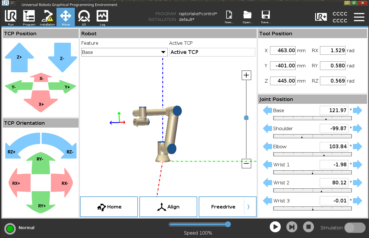
Converting Universal Robots teach pendant tool positions to ROS 2 coordinate conventions#
Set the pendant coordinate feature dropdown to base.
Note the pendant Cartesian position $(X, Y, Z)$ and convert to ROS 2 meters: $$X_{\text{ros}} = -X_{\text{pendant}},\quad Y_{\text{ros}} = -Y_{\text{pendant}},\quad Z_{\text{ros}} = Z_{\text{pendant}}$$
Convert Axis-Angle rotation vectors to unit quaternions $(q_x, q_y, q_z, q_w)$, applying sign inversions: $$\mathbf{q}_{\text{ros}} = [-q_y, q_x, q_w, -q_z]$$
Record the final pose array
[X, Y, Z, q_x, q_y, q_z, q_w]inwaypoint.yaml:/**: ros__parameters: safe_point_pose: [-0.463098, 0.401034, 0.444935, -0.254744, 0.672562, 0.648287, -0.249979] drop_point_pose: [-0.340000, 0.540000, 0.248000, -0.104535, 0.783149, 0.603396, -0.107991]
Build and Launch Procedure#
1. Build the Workspace#
Source the ROS 2 Jazzy environment and build the Stationary Robot Toolkit:
source /opt/ros/jazzy/setup.bash
colcon build --base-paths src --symlink-install
source install/setup.bash
2. Launch the Application#
Ensure the robot and camera are connected and configured as described in the UR5e Vision and Controls Deployment Configuration.
Open three terminals (sourcing install/setup.bash in each):
Terminal 1: RViz2 Visualization & Motion Planning Scene
ros2 launch stationary_robotics_dynamic_demo rviz2_launch.py
Terminal 2: Vision & AI Perception Pipeline
ros2 launch stationary_robotics_vision_main vision.composition.launch.py
Terminal 3: Dynamic State Machine & Motion Control
ros2 launch stationary_robotics_dynamic_demo dynamic_demo_launch.py \
  robot_ip:=<ROBOT_IP> \
  rs_model:=d415 \
  motion_controller:=servo
Once all nodes are initialized, press Play on the UR5e teach pendant program running external_control.urcap.
Next Steps: Swapping Hardware Components#
The Stationary Robot Toolkit provides a modular interface abstraction allowing developers to customize cameras, manipulators, and end effectors.
1. Swapping Camera Models and Positions#
To use a different RealSense model (e.g., D435, D455) or relocate the camera:
Create a custom XACRO file defining the new camera pose relative to the robot base:
<origin xyz="0.330 0.721 0.755" rpy="-3.14159 1.5708 -1.5708"/>
Update the
z_thresholdparameter inparameters.yamlto ensure the point cloud cropping boundary matches the distance from the new camera position to the work surface.If using a third-party RGB-D camera, verify that the ROS 2 driver publishes ordered
sensor_msgs/PointCloud2streams with optical frame metadata matching the camera URDF.
2. Swapping Universal Robot Manipulators#
The default deployment targets the UR5e. To adapt the pipeline for a larger or smaller arm from the same family (e.g., UR10e, UR16e):
Pass the target arm model via the launch argument:
ros2 launch stationary_robotics_dynamic_demo dynamic_demo_launch.py \
  robot_ip:=<ROBOT_IP> \
  ur_type:=ur10e
Ensure the corresponding kinematics calibration file for the new arm is loaded in the driver description.
3. Integrating Custom Grippers and End Effectors#
When substituting the Robotiq 2F-85 with a custom pneumatic or electric gripper:
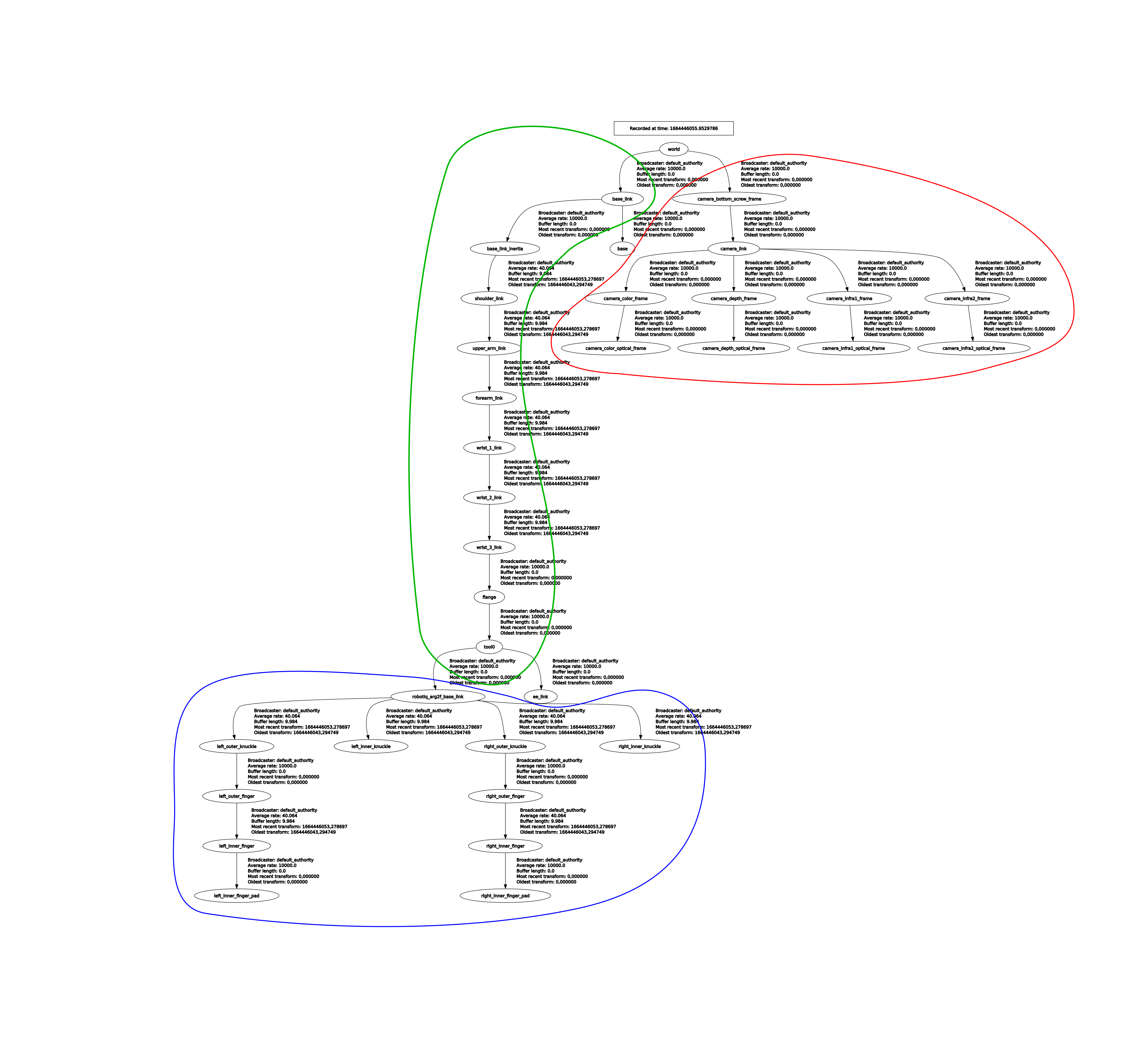
Build a composite URDF/XACRO file that attaches the new gripper base link to the robot’s
tool0flange.If the gripper driver uses
ros2_control, expose the active joints in the hardware configuration.Compute the new Tool Center Point (TCP) z-offset (distance from
tool0to the grasping point) and updateee_linkin the MoveIt 2 configuration.
ROS 2 TF transformation hierarchy for the composite manipulator and gripper#