GMSL#
This guide covers connecting and configuring a GMSL camera using the AAEON CEXD-INTRBL FAKRA ports. Use of this interface requires software setup, including installing the Robotics AI Suite. Make sure you’ve followed the Getting Started guide.
Physical Connection#
The AAEON CEXD-INTRBL development kit includes a built-in GMSL connector board. You can see two FAKRA connectors exposed on the external housing. These support up to 8 connections, split between both ports.
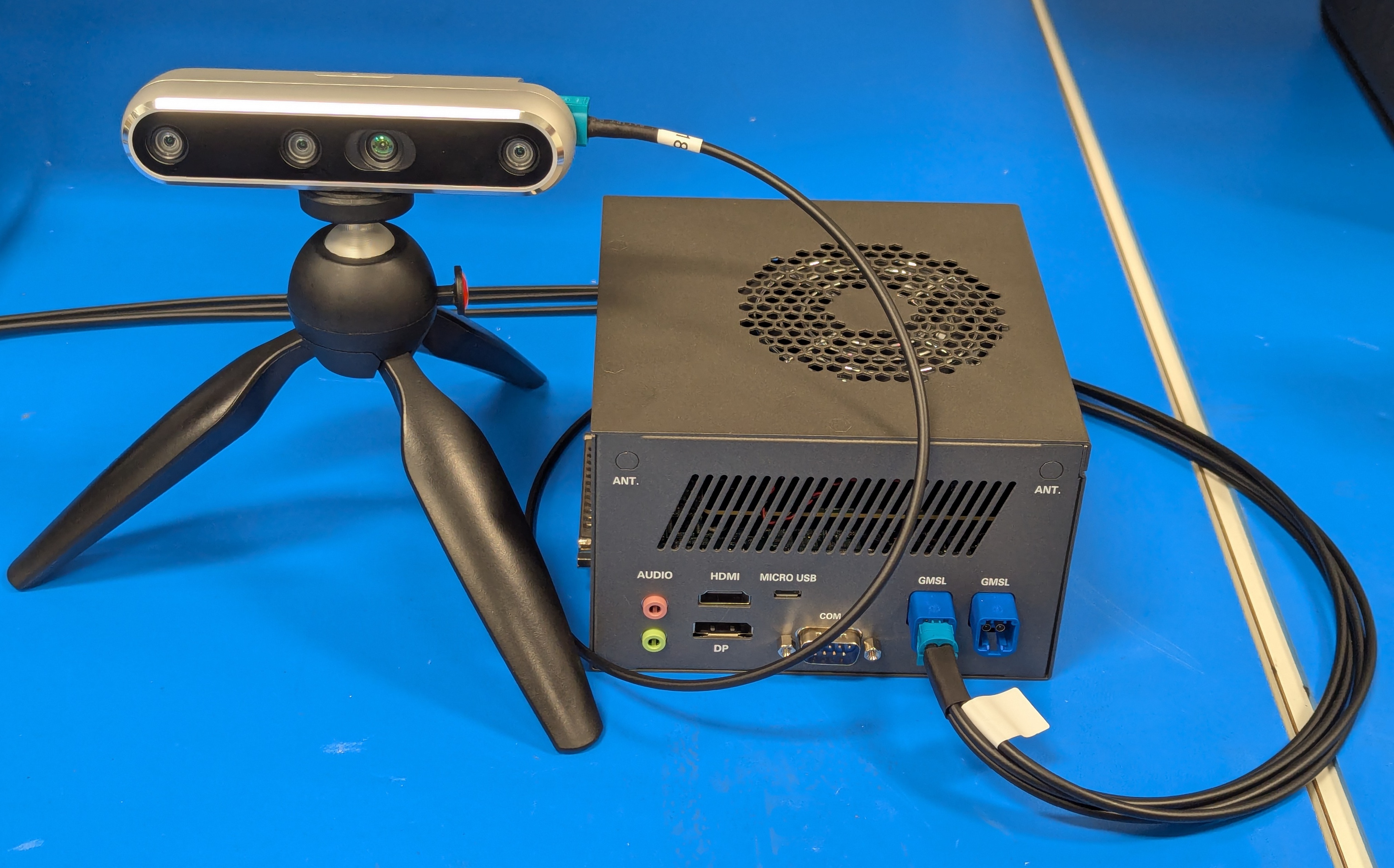
For RealSense D457 GMSL cameras, connect a maximum of 2 cameras to each GMSL 4-in-1 FAKRA port. This optimizes bandwidth for the multi-sensor devices. Additional connections for this camera is not currently supported by Robotics AI Suites, and may not be supported by the manufacturer.
BIOS Configuration#
You can access the ACPI GMSL settings under the System IO menu.
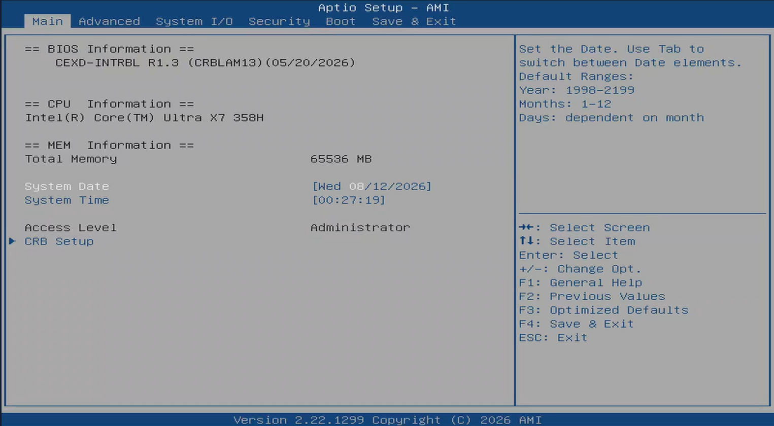
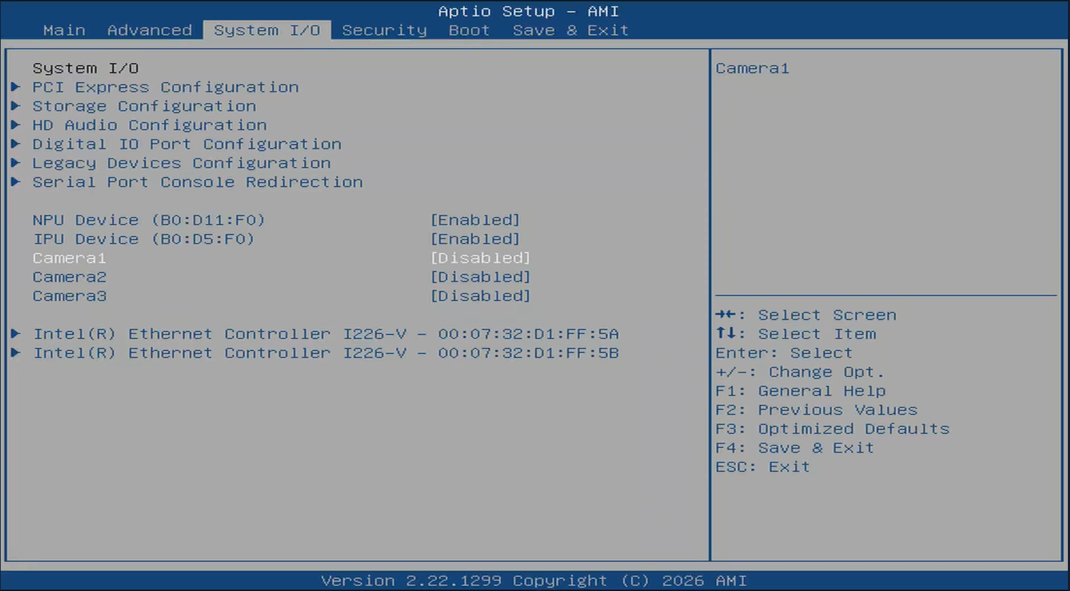
Select Camera1 and select Enabled.
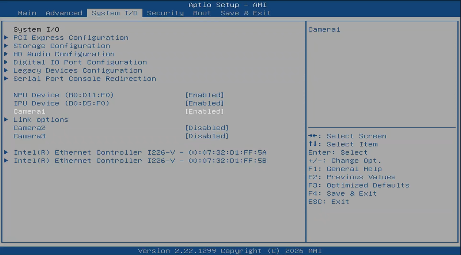
This will expose an additional menu called Link options.
Enter Link options to update the ACPI GMSL settings for your sensor.
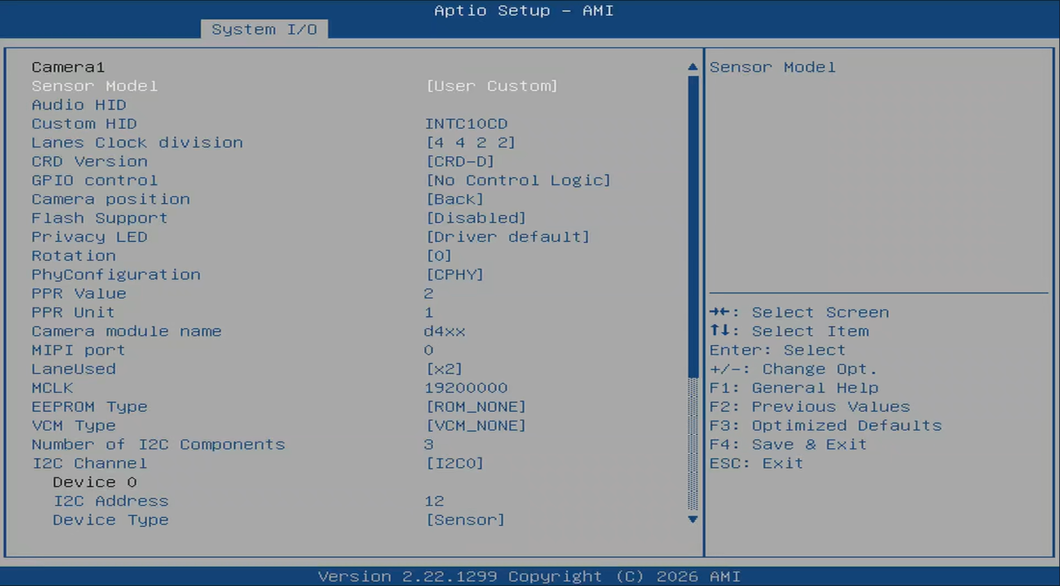
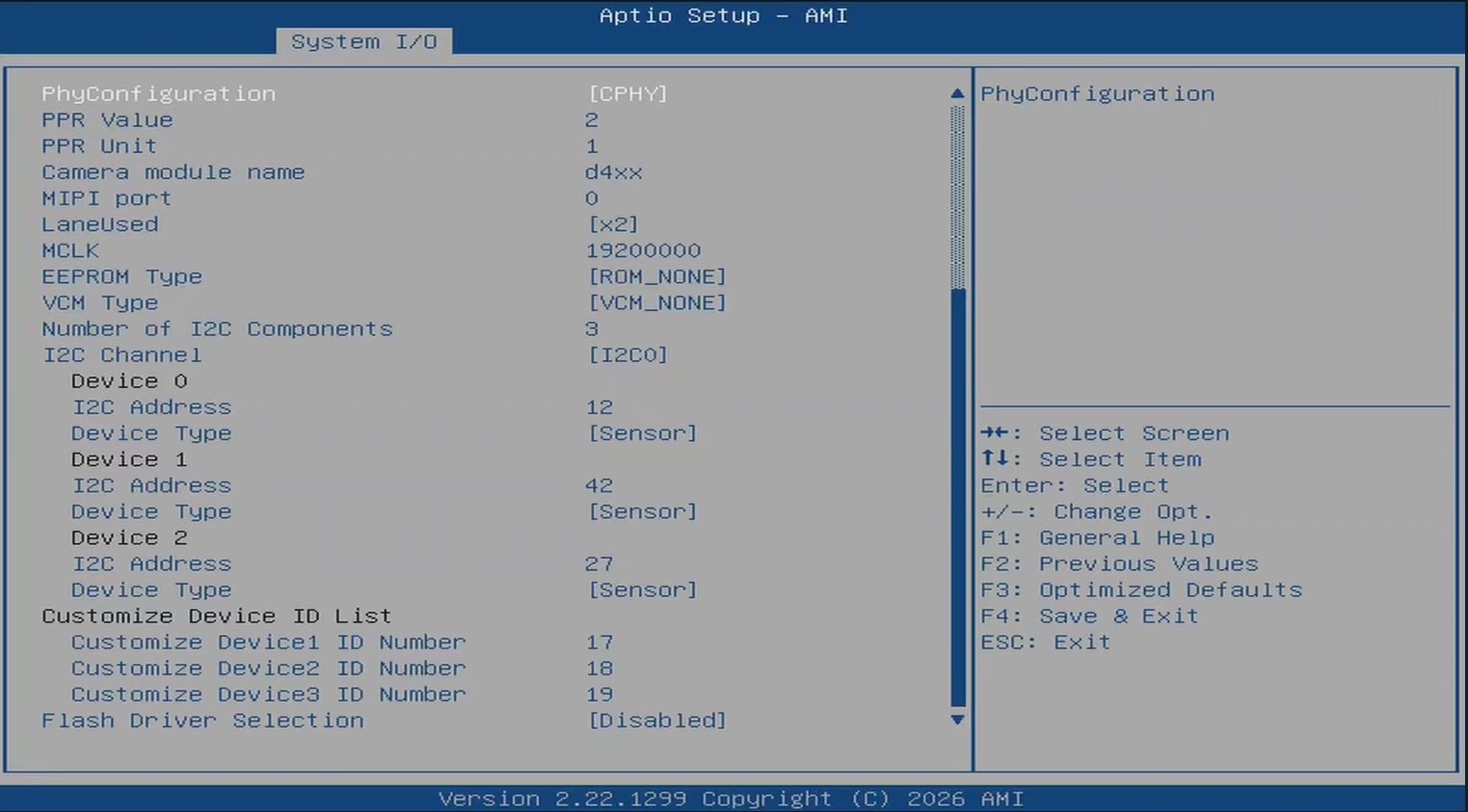
Modify these values according to the information below. Your settings may vary depending on sensor manufacturer.
This table is a validated example of ACPI GMSL settings for the RealSense D457
Here, 4 individual cameras are setup, split across both FAKRA connectors. This enables the maximum bandwidth and compatibility for the multi-sensor devices. Additional D457 GMSL connections are not currently supported. For simplicity, the top two GMSL ports (rotation 90 and 180) are used.
Camera 1 |
Camera 2 |
Camera 3 |
Camera 4 |
|
|---|---|---|---|---|
Sensor Model |
User Custom |
User Custom |
User Custom |
User Custom |
Custom HID |
|
|
|
|
Lanes Clock division |
4 4 2 2 |
4 4 2 2 |
4 4 2 2 |
4 4 2 2 |
CRD Version |
CRD-D |
CRD-D |
CRD-D |
CRD-D |
GPIO control |
No Control Logic |
No Control Logic |
No Control Logic |
No Control Logic |
Camera position |
Back |
Back |
Front |
Front |
Flash Support |
Disabled |
Disabled |
Disabled |
Disabled |
Privacy LED |
Disabled |
Disabled |
Disabled |
Disabled |
Rotation |
90 |
180 |
90 |
180 |
PhyConfiguration |
CPHY |
CPHY |
CPHY |
CPHY |
PPR Value |
2 |
2 |
2 |
2 |
PPR Unit |
1 |
1 |
1 |
1 |
Camera module name |
|
|
|
|
MIPI port |
0 |
0 |
2 |
2 |
LaneUsed |
x2 |
x2 |
x2 |
x2 |
MCLK |
19200000 |
19200000 |
19200000 |
19200000 |
EEPROM Type |
ROM_NONE |
ROM_NONE |
ROM_NONE |
ROM_NONE |
VCM Type |
VCM_NONE |
VCM_NONE |
VCM_NONE |
VCM_NONE |
Number of I2C Components |
3 |
3 |
3 |
3 |
I2C Channel |
I2C0 |
I2C0 |
I2C1 |
I2C1 |
Device0 I2C Address |
12 |
14 |
12 |
14 |
Device1 I2C Address |
42 |
44 |
42 |
44 |
Device2 I2C Address |
27 |
27 |
27 |
27 |
This table is a validated configuration of ACPI GMSL settings for the D3 Embedded Discovery GMSL2 camera module.
When using the D3 GMSL2 series camera, set the ACPI GMSL settings according to the port being used. Camera1 below sets up all D3 GMSL2 cameras on the left GMSL port. You only need the settings for a single sensor to enable all connected sensors. Camera2 does the same for the right port. In this case, the rotation value is ignored.
UEFI Custom Sensor |
Camera1 |
Camera2 |
|---|---|---|
Custom HID |
|
|
Lanes Clock Division |
4 4 2 2 |
4 4 2 2 |
CRD Version |
CRD-D |
CRD-D |
GPIO Control |
No Control Logic |
No Control Logic |
Camera Position |
Back |
Front |
Flash Support |
Disabled |
Disabled |
Privacy LED |
Disabled |
Disabled |
Rotation |
0 |
0 |
Voltage Rail |
3 |
3 |
PhyConfiguration |
CPHY |
CPHY |
PPR Value |
2 |
2 |
PPR Unit |
4 |
4 |
Camera module label |
|
|
MIPI Port (Index) |
0 |
2 |
LaneUsed |
x4 |
x4 |
MCLK |
19200000 |
19200000 |
EEPROM |
ROM_NONE |
ROM_NONE |
VCM TYPE |
VCM_NONE |
VCM_NONE |
Number of I2C |
3 |
3 |
I2C Channel |
I2C0 |
I2C1 |
Device0 I2C Address |
27 |
27 |
Device1 I2C Address |
44 |
44 |
Device2 I2C Address |
54 |
54 |
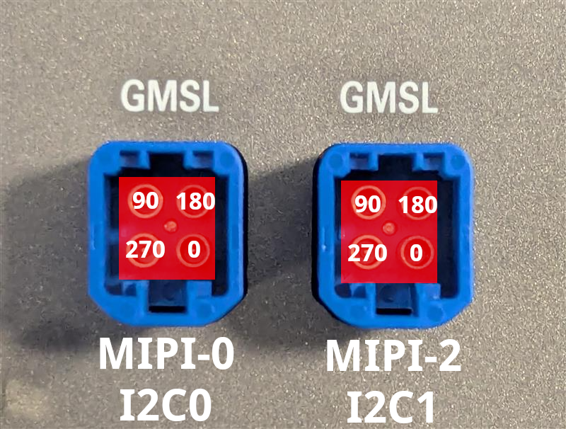
The active mini-FAKRA port is determined by the rotation value. Below is a table showing the default rotation per port location.
Rotation |
Port |
|---|---|
270 |
Lower-left |
90 |
Upper-left |
180 |
Upper-right |
0 |
Lower-right |
Here is an image overlaid with the correct rotation values, MIPI port, and I2C bus for reference:
Next steps#
Once you’ve setup your ACPI GMSL settings for your camera, continue with Step 2: GMSL Software Driver