GMSL Cameras#
Gigabit Multimedia Serial Link (GMSL) is a high-speed serial interface for
connecting cameras to a processing platform. This guide covers supported camera
modules, GMSL Add-in-Card design, and GMSL SerDes configuration.
Supported GMSL Cameras#
Camera |
Supported Development Kit |
Interface |
Type |
Sensor |
Vendor |
|---|---|---|---|---|---|
RealSense D457 |
AAEON CEXD-INTRBL |
GMSL |
Depth · Color |
OV9782 + D450 Depth |
|
D3 Embedded D3CMCXXX-115-084 |
AAEON CEXD-INTRBL |
GMSL |
Color |
ISX031 |
Enabling GMSL Camera#
Follow this guide to enable a GMSL camera for your development kit.
Step 1: Configure BIOS#
Find the GMSL guide for your specific Development Kit in the table below and complete it.
Development Kit |
GMSL Guide |
|---|---|
AAEON CEXD-INTRBL |
Step 2: GMSL Software Driver#
Install Driver Package#
After the system has been rebooted, install the GMSL driver by running the following command:
NOTE: Prerequisites for the GMSL driver can be found in the Getting Started guide.
sudo apt-get update
sudo apt-get install ffmpeg # for stream verification
sudo apt-get install intel-mipi-gmsl-dkms
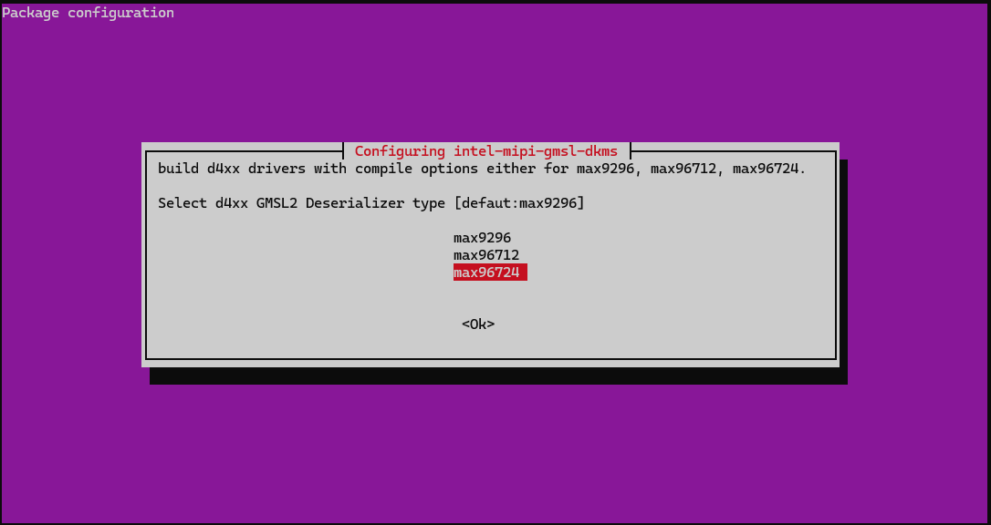
During installation, intel-mipi-gmsl-dkms presents a configuration dialog prompting you to select the deserializer model.
Select the appropriate deserializer based on the your system’s IPU below. Unlisted platforms may be unsupported:
Code Name |
Intel Processor |
IPU Version |
Deserializer |
|---|---|---|---|
Panther Lake |
Series 3 Intel® Core™ Ultra Processor |
IPU7 |
|
Arrow Lake |
Series 2 Intel® Core™ Ultra Processor |
IPU6 |
|
Reboot#
A reboot is required after installing the driver package.
Step 3: Bind GMSL camera#
First, load the IPU driver:
sudo modprobe intel-ipu7-isys
sudo modprobe intel-ipu6-isys
Camera binding involves using mediactl to correctly setup the GMSL cameras, and create a symbolic link.
Helper scripts are provided for you, with variations based on supported sensor. You can find them here:
/usr/share/camera/
Note
If you are configuring both D3 and RealSense cameras on the same system, you must bind the D3 cameras before the RealSense cameras. Failure to bind the cameras in the correct order will result in missing media devices.
The following scripts are used for Realsense D457. Execute both in the order given below:
sudo /usr/share/camera/rs_ipu_d457_bind.sh
You should see console output similar to the following for a RealSense D457. This may vary by camera and manufacturer:
intel@intel-CEXD-INTRBL:~$ sudo /usr/share/camera/rs_ipu_d457_bind.sh
/dev/media0
find /dev -type l -name *video-rs* -delete            RET=0
Bind IPU7 to DS5 mux c-2 ...(count=1 on IPU7 CSI 2)...
/usr/bin/media-ctl -d /dev/media0 -v -l "Intel IPU7 CSI2 2":2 -> "Intel IPU7 ISYS Capture 33":0[1]            RET=0
/usr/bin/media-ctl -d /dev/media0 -v -l "Intel IPU7 CSI2 2":4 -> "Intel IPU7 ISYS Capture 35":0[1]            RET=0
/usr/bin/media-ctl -d /dev/media0 -v -l "Intel IPU7 CSI2 2":13 -> "Intel IPU7 ISYS Capture 44":0[1]            RET=0
/usr/bin/media-ctl -d /dev/media0 -v -l "Intel IPU7 CSI2 2":14 -> "Intel IPU7 ISYS Capture 45":0[1]            RET=0
/usr/bin/media-ctl -d /dev/media0 -l "DS5 mux c-2":0 -> "Intel IPU7 CSI2 2":0[1]            RET=0
/usr/bin/media-ctl -d /dev/media0 -R "DS5 mux c-2"[1/1->0/1[1], 2/3->0/3[1], 3/12->0/12[1], 4/13->0/13[1]]            RET=0
/usr/bin/media-ctl -d /dev/media0 -R "Intel IPU7 CSI2 2"[0/1->2/1[1], 0/3->4/3[1], 0/12->13/12[1], 0/13->14/13[1]]            RET=0
/usr/bin/media-ctl -d /dev/media0 -V "Intel IPU7 CSI2 2":2/1 [fmt:UYVY8_1X16/640x480 field:none]            RET=0
/usr/bin/media-ctl -d /dev/media0 -V "DS5 mux c-2":0/1 [fmt:UYVY8_1X16/640x480@1/30 field:none]            RET=0
/usr/bin/media-ctl -d /dev/media0 -V "DS5 mux c-2":1/1 [fmt:UYVY8_1X16/640x480@1/30 field:none]            RET=0
/usr/bin/media-ctl -d /dev/media0 -V "D4XX depth c-2":0/1 [fmt:UYVY8_1X16/640x480@1/30 field:none]            RET=0
/usr/bin/media-ctl -d /dev/media0 -V "Intel IPU7 CSI2 2":4/3 [fmt:YUYV8_1X16/640x480 field:none]            RET=0
/usr/bin/media-ctl -d /dev/media0 -V "DS5 mux c-2":0/3 [fmt:YUYV8_1X16/640x480@1/30 field:none]            RET=0
/usr/bin/media-ctl -d /dev/media0 -V "DS5 mux c-2":2/3 [fmt:YUYV8_1X16/640x480@1/30 field:none]            RET=0
/usr/bin/media-ctl -d /dev/media0 -V "D4XX rgb c-2":0/3 [fmt:YUYV8_1X16/640x480@1/30 field:none]            RET=0
/usr/bin/media-ctl -d /dev/media0 -V "Intel IPU7 CSI2 2":13/12 [fmt:VYUY8_1X16/640x480 field:none]            RET=0
/usr/bin/media-ctl -d /dev/media0 -V "DS5 mux c-2":0/12 [fmt:VYUY8_1X16/640x480@1/30 field:none]            RET=0
/usr/bin/media-ctl -d /dev/media0 -V "DS5 mux c-2":3/12 [fmt:VYUY8_1X16/640x480@1/30 field:none]            RET=0
/usr/bin/media-ctl -d /dev/media0 -V "D4XX ir c-2":0/12 [fmt:VYUY8_1X16/640x480@1/30 field:none]            RET=0
/usr/bin/media-ctl -d /dev/media0 -V "Intel IPU7 CSI2 2":14/13 [fmt:Y8_1X8/38x1 field:none]            RET=0
/usr/bin/media-ctl -d /dev/media0 -V "DS5 mux c-2":0/13 [fmt:Y8_1X8/38x1@1/30 field:none]            RET=0
/usr/bin/media-ctl -d /dev/media0 -V "DS5 mux c-2":4/13 [fmt:Y8_1X8/38x1@1/30 field:none]            RET=0
/usr/bin/media-ctl -d /dev/media0 -V "D4XX imu c-2":0/13 [fmt:Y8_1X8/38x1@1/30 field:none]            RET=0
Next, bind the device files to reusable symlinks:
sudo /usr/share/camera/rs-enum-ipu.sh
You should see output similar to:
intel@intel-CEXD-INTRBL:~$ sudo /usr/share/camera/rs-enum-ipu.sh
Bus     Camera  Sensor  Node Type       Video Node      RS Link
ipu7   c-2     ir      Stream(id=12)   /dev/video44    /dev/video-rs-ir-10     [640/480]
ipu7   c-2     depth   Stream(id=1)    /dev/video33    /dev/video-rs-depth-10  [640/480]
ipu7   c-2     imu     Stream(id=13)   /dev/video45    /dev/video-rs-imu-10    [38/1]
ipu7   c-2     color   Stream(id=3)    /dev/video35    /dev/video-rs-color-10  [640/480]
i2c    c-2     d4xx    Firmware        /dev/d4xx-dfu-c-2       /dev/d4xx-dfu-10
Execute the following script for D3 and other cameras:
sudo /usr/share/camera/ipu_max9x_bind.sh
Step 4: Verify Camera#
Verify the camera(s) are available in /dev/video:
ls -la /dev/video-rs-*
You should see output similar to:
lrwxrwxrwx 1 root root 12 Aug 10 16:39 /dev/video-rs-color-10 -> /dev/video35
lrwxrwxrwx 1 root root 12 Aug 10 16:39 /dev/video-rs-depth-10 -> /dev/video33
lrwxrwxrwx 1 root root 12 Aug 10 16:39 /dev/video-rs-imu-10 -> /dev/video45
lrwxrwxrwx 1 root root 12 Aug 10 16:39 /dev/video-rs-ir-10 -> /dev/video44
Verify the camera(s) are available in /dev/video:
ls -la /dev/video*
You should see output similar to:
lrwxrwxrwx 1 root root 11 Jul 14 15:23 /dev/video-isx031-a-0 -> /dev/video0
Step 5: Test Camera Data#
Confirm that you can query camera capabilities using v4l2-ctl, and stream frame data. Your bound device might use a different label then what is shown:
sudo v4l2-ctl -d /dev/video-rs-color-10 --stream-mmap --verbose
sudo v4l2-ctl -d /dev/video-isx031-1-0 --stream-mmap --verbose
You should see output similar to:
VIDIOC_QUERYCAP: ok
                VIDIOC_REQBUFS returned 0 (Success)
                VIDIOC_CREATE_BUFS returned 0 (Success)
                VIDIOC_QUERYBUF returned 0 (Success)
                VIDIOC_QUERYBUF returned 0 (Success)
                VIDIOC_QUERYBUF returned 0 (Success)
                VIDIOC_QUERYBUF returned 0 (Success)
                VIDIOC_G_FMT returned 0 (Success)
                VIDIOC_QBUF returned 0 (Success)
                VIDIOC_QBUF returned 0 (Success)
                VIDIOC_QBUF returned 0 (Success)
                VIDIOC_QBUF returned 0 (Success)
                VIDIOC_STREAMON returned 0 (Success)
cap dqbuf: 0 seq:      0 bytesused: 614400 ts: 294.387553 field: None (ts-monotonic, ts-src-eof)
cap dqbuf: 1 seq:      1 bytesused: 614400 ts: 294.420904 delta: 33.351 ms field: None (ts-monotonic, ts-src-eof)
cap dqbuf: 2 seq:      2 bytesused: 614400 ts: 294.454255 delta: 33.351 ms field: None (ts-monotonic, ts-src-eof)
cap dqbuf: 3 seq:      3 bytesused: 614400 ts: 294.487605 delta: 33.350 ms field: None (ts-monotonic, ts-src-eof)
cap dqbuf: 0 seq:      4 bytesused: 614400 ts: 294.520956 delta: 33.351 ms fps: 29.98 field: None (ts-monotonic, ts-src-eof)
cap dqbuf: 1 seq:      5 bytesused: 614400 ts: 294.554306 delta: 33.350 ms fps: 29.98 field: None (ts-monotonic, ts-src-eof)
cap dqbuf: 2 seq:      6 bytesused: 614400 ts: 294.587657 delta: 33.351 ms fps: 29.98 field: None (ts-monotonic, ts-src-eof)
cap dqbuf: 3 seq:      7 bytesused: 614400 ts: 294.621007 delta: 33.350 ms fps: 29.98 field: None (ts-monotonic, ts-src-eof)
cap dqbuf: 0 seq:      8 bytesused: 614400 ts: 294.654358 delta: 33.351 ms fps: 29.98 field: None (ts-monotonic, ts-src-eof)
Step 6: Capture a Live Image#
Your camera is now setup. This is a good chance to fetch a live image from your camera. You can use ffmpeg to fetch a frame or display a live vide.
Capture a single frame with ffmpeg and view it:
ffmpeg -f v4l2 -i /dev/video-rs-color-10 -frames:v 1 frame.jpg
xdg-open frame.jpg
Or view the live video stream with ffplay:
ffplay -f v4l2 -i /dev/video-rs-color-10
Alternatively, capture a single frame with ffmpeg and view it:
ffmpeg -f v4l2 -i /dev/video-isx031-a-0 -frames:v 1 frame.jpg
xdg-open frame.jpg
Or view the live video stream with ffplay:
ffplay -f v4l2 -i /dev/video-isx031-a-0
Next Steps#
Now that your GMSL camera is properly connected, you can test out using it with various samples or immediately use in your robotics solution:
Use OpenVINO to stream GMSL video data into a YOLO-based computer vision sample: OpenVINO RealSense AI Demo
Use ROS 2 to ingest camera frames for use in a ROS-powered application: RealSense ROS2 Node