UR5e Vision and Controls Deployment Configuration#
The Universal Robots UR5e with Robotiq 2F-85 gripper and Intel RealSense camera provides a verified hardware and software baseline for vision-guided pick-and-place workflows with the Stationary Robot Toolkit.
Hardware Bill of Materials#
Component |
Model / Specification |
Purpose |
|---|---|---|
Host Compute |
Intel Core Ultra Series 3 platform |
Runs ROS 2 Jazzy, AI perception pipeline, MoveIt 2 Servo orchestration, and robot driver nodes |
Manipulator |
Universal Robots UR5e (e-Series, 6-DoF) |
Physical manipulation and trajectory execution |
End Effector |
Robotiq 2F-85 Adaptive Gripper |
Two-finger parallel gripping |
Camera |
Intel RealSense Depth Camera (e.g., D415 / D435 / D455) |
Overhead RGB and depth streaming for 2D/3D perception |
Interface Network |
Dedicated Gigabit Ethernet cable |
Low-latency private network connecting host compute and UR5e control box |
Network Configuration#
The Universal Robots controller requires a dedicated, low-latency point-to-point Ethernet connection with the host compute.
Connect the host computer Ethernet port directly to the UR5e control box Ethernet port.
Configure a static IP subnet on the host network adapter (for example,
192.168.1.100with subnet mask255.255.255.0).On the UR teach pendant, navigate to Settings > System > Network and assign a static IP within the same subnet (for example,
192.168.1.102).Test connectivity from the host terminal:
ping -c 3 192.168.1.102
Teach Pendant and URCap Setup#
1. External Control URCap#
The external_control.urcap enables the ROS 2 UR driver (ur_robot_driver) to take control of trajectory execution from the teach pendant.
Download the latest
external_control.urcapfrom the Universal Robots ROS 2 Driver repository.Copy the
.urcapfile to a USB flash drive and plug it into the teach pendant.On the teach pendant, select Settings > System > URCaps, tap
+, selectexternal_control.urcap, and restart the controller when prompted.Go to Installation > URCaps > External Control:
Set the Host IP to your host compute IP address (e.g.,
192.168.1.100).Set the Custom port to
50002.Set Host name to your preferred host identifier.
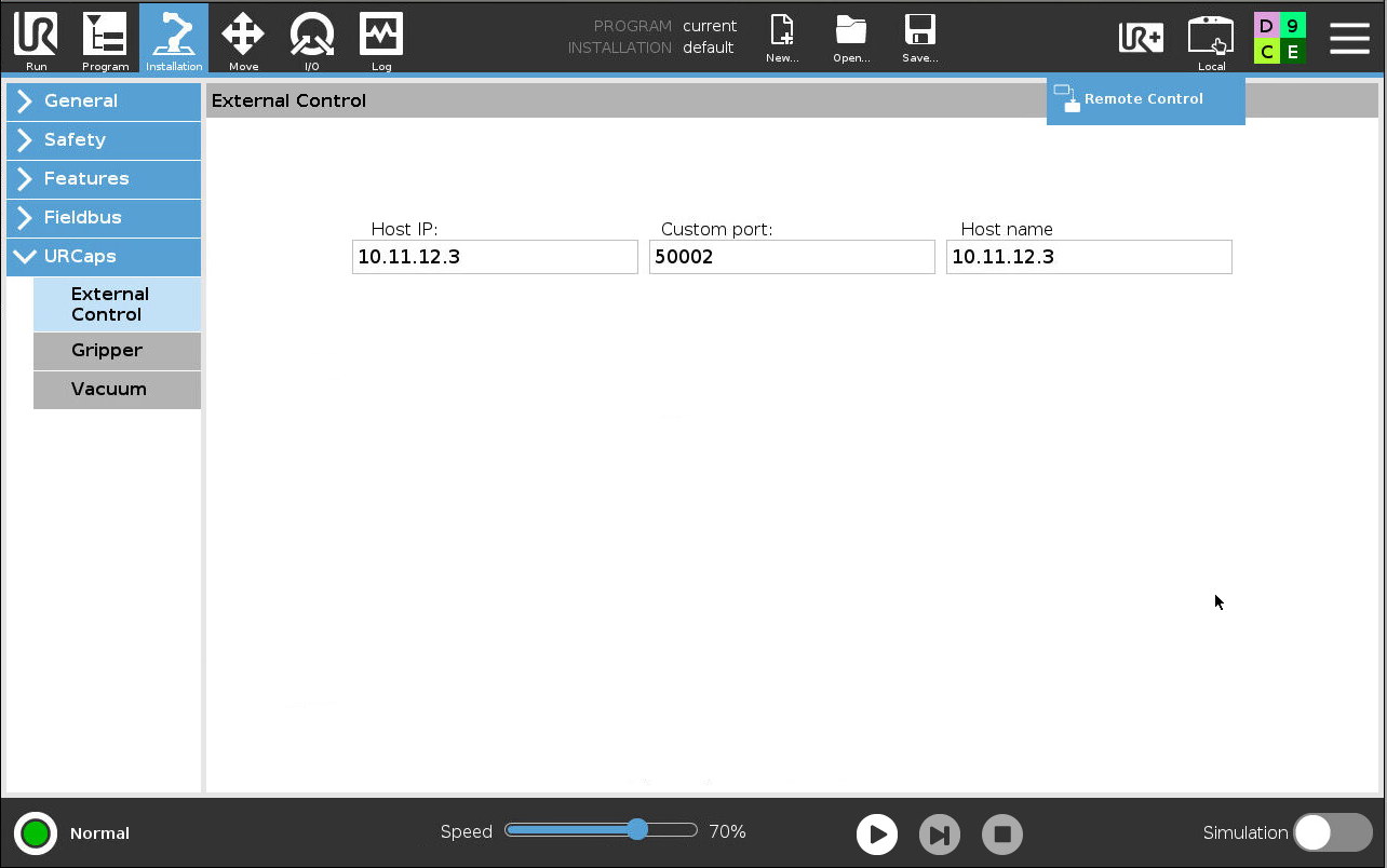
Configuring External Control URCap on the UR teach pendant#
2. Robotiq Gripper URCap#
Download the Robotiq 2F-85/2F-140 URCap package from Robotiq support.
Install the URCap via Settings > System > URCaps on the teach pendant and restart the robot.
Verify gripper activation under the Installation > URCaps > Gripper tab.
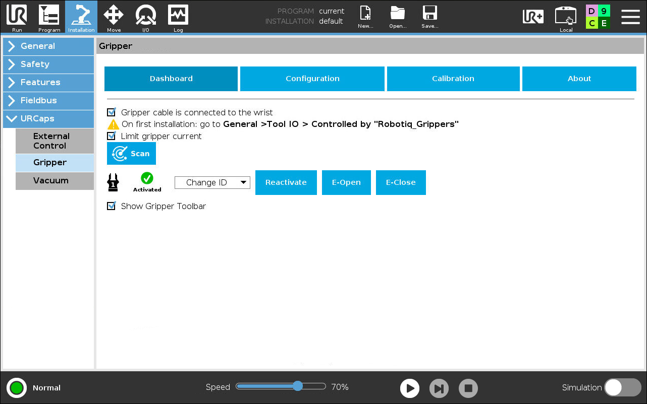
Robotiq Gripper setup on the UR teach pendant#
3. Operational Safety and Speed Limits#
Warning
During initial commissioning and calibration, set the physical teach pendant Speed Slider and the RViz2 motion scaling to $\le 70%$. Operating unvalidated motion trajectories at maximum velocity can cause excessive torque and stress on workstation mounting bolts and work cell fixtures.
Kinematics Calibration Extraction#
Every UR arm possesses slight physical manufacturing tolerances recorded during factory calibration. Extracting this calibration into your ROS 2 environment avoids accumulating inverse kinematics errors during precise grasping.
Ensure the robot is powered on and connected via Ethernet.
Run the calibration extraction launch file:
ros2 launch ur_calibration calibration_correction.launch.py \
  robot_ip:=192.168.1.102 \
  target_filename:="${HOME}/my_ur5e_calibration.yaml"
Pass the generated calibration file to the UR description and driver launch files when starting robot bring-up.
Camera Setup and Extrinsics Registration#
1. Camera Interface Verification#
The Intel RealSense camera streams RGB and depth point clouds to the perception pipeline over USB 3.2.
Connect the RealSense camera using a USB 3.2-rated Type-C cable to a high-speed host USB port.
Verify that the device is detected on a SuperSpeed (USB 3.2) link:
rs-enumerate-devices | grep -i "USB"
2. Camera-to-World Transform (XACRO Origin)#
Perception outputs poses in the optical frame of the camera. To allow the motion controller to navigate the arm to detected targets, the camera’s spatial transform relative to the robot world / base_link frame must be defined in the cell XACRO model:
<robot name="d415_camera" xmlns:xacro="http://ros.org/wiki/xacro">
    <xacro:arg name="use_nominal_extrinsics" default="false"/>
    <xacro:arg name="name" default="cameraipc0"/>
    <xacro:include filename="$(find realsense2_description)/urdf/_d415.urdf.xacro" />
    <link name="world" />
    <xacro:sensor_d415 parent="world" name="$(arg name)" use_nominal_extrinsics="$(arg use_nominal_extrinsics)">
        <origin xyz="0.36 0.66 0.755" rpy="-3.141592654 1.570796327 -1.570796327"/>
    </xacro:sensor_d415>
</robot>
The
xyzcoordinate $(0.36, 0.66, 0.755)$ specifies the camera translation in meters relative to the robot base frame.The
rpyangles $(-3.14159, 1.5708, -1.5708)$ define the orientation in radians.
3. Tool Center Point (TCP) Offset#
When the Robotiq 2F-85 gripper is attached to the UR5e tool0 flange, the grasping center between the fingertips is offset along the z-axis:
$$\Delta z = 0.174\text{ m}\quad (17.4\text{ cm})$$
Configure this offset in the robot URDF/SRDF and the teach pendant TCP settings to ensure accurate approach calculations.
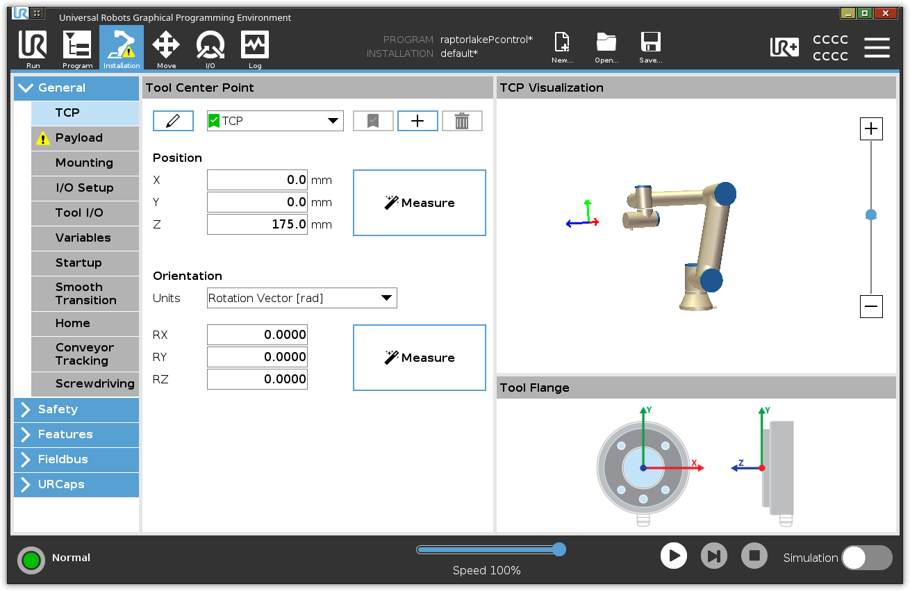
TCP offset configuration for the Robotiq 2F-85 gripper#
Next Steps#
Once the hardware baseline and network connection are verified, proceed to:
Validate trajectory execution safely in Stationary Robotics Toolkit Simulation.
Execute the end-to-end vision-guided pick-and-place application in the Stationary Robot Toolkit Vision and Controls Deployment Demo.