RTmotion Concept and Application Interface#
The PLCopen motion standard provides a way to have standard and modular application libraries that are reusable for multiple industrial automation scenarios, such as PLC motion control, CNC, and robotics. For more detailed information of the PLCopen motion specifications, please refer to the Motion Control Standards.
1. RTmotion Overview#
The motion control market displays a wide variety of incompatible systems and solutions. In businesses where different systems are used, this incompatibility induces considerable costs for the end-users, learning is confusing, engineering becomes difficult, and the process of market growth slows down. Standardization would certainly reduce these negative factors. Standardization means not only the programming languages themselves, (as standardization is achieved using the worldwide IEC 61131-3 standard) but also standardizing the interface towards different motion control solutions. In this way the programming of these motion control solutions is less hardware dependent. The reusability of the application software is increased, and the costs involved in training and support are reduced.
RTmotion is an C++ library created by Intel Corporation. RTmotion implements part of the single axis motion control function blocks defined in parts 1&2 (PDF), 3 (PDF) and 5 (PDF) of PLCopen motion control standard. The figure below shows the connections between RTmotion and other components in Intel® Edge Controls for Industrial.
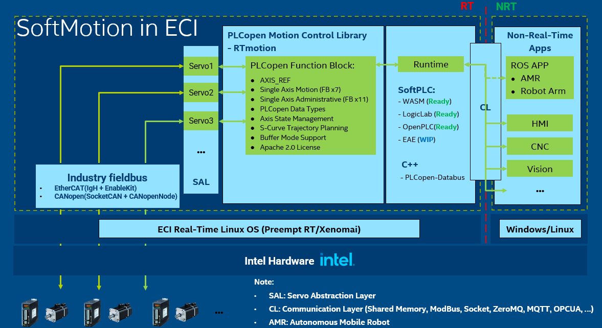
Figure 1. ECI SoftMotion overview
RTmotion is a library designed to match the interfaces and functions of the function blocks defined in PLCopen standard. It is not tied to any operating system, fieldbus, SoftPLC or applications. But it needs to run in a real-time thread to have steady cycle and gain maximum performance. So the real-time operating systems are the base foundation for RTmotion to run on. As figure above shows, Intel® Edge Controls for Industrial provides two types of real-time operating systems (Preempt RT, Xenomai) that RTmotion can fit in.
RTmotion provides functions and algorithms for performing motion control tasks according to the PLCopen standard. It requires reading status from servo motors and outputting motion commands to them. The bridge between RTmotion and servo motors is implemented in a hardware abstraction layer called plcopen-servo. It is based on a servo template that can be populated by different fieldbus communication stack interfaces to derive the servo motor of a specific fieldbus type. As shown in the figure, Intel® Edge Controls for Industrial provides two types of servo layers (CANopen and EtherCAT). Details of plcopen-servo are covered in level-2.
RTmotion’s functional blocks often play the role of basic modules that can be integrated like Lego blocks to create complex applications. The C++ API of RTmotion can be called in different ways:
Called in a C++ application: Intel® Edge Controls for Industrial provides examples in plcopen-servo and plcopen-databus repositories for reference.
Integrated in a SoftPLC runtime: RTmotion has been integrated in several commercial and open-source SoftPLC runtime. See the list below.
WASM (Further reading for WASM)
LogicLab (Further reading for LogicLab + RTmotion)
OpenPLC (Further reading for OpenPLC + RTmotion)
EcoStruxure* Automation Expert (WIP, further reading for EAE).
RTmotion provides basic trajectory interpolation and motion control in real-time tasks synchronized with the servo motor cycle time. As shown in the right part of the figure, the real-time tasks usually require to communicate with some non-real-time software (advanced robotics motion planning, SCADA HMI, CNC and machine vision) in some application scenarios. It can be realized by using a communication layer in the databus form of Shared-Memory, Modbus, Socket, ZeroMQ, MQTT, OPCUA, etc.
1.1. RTmotion Requirements#
PC: Industrial PC with Intel® CPU
RTOS: Intel® Edge Controls for Industrial Preempt RT/Xenomai
Fieldbus: Intel® Edge Controls for Industrial EtherCAT/CANopen stack
1.2. RTmotion Features#
PLCopen Data Types
AXIS_REF: Defined as a pointer to an axis. Since AXIS_REF is used as a VAR_IN_OUT variable in the function block, and any function block can access and change the status of the axis, function block scheduling and management are implemented in the axis to avoid potential errors when modifying the axis at the same time.MC_AXIS_STATES:mcDisabled
mcStandstill
mcHoming
mcDiscreteMotion
mcContinuousMotion
mcSynchronizedMotion
mcStopping
mcErrorStop
MC_DIRECTION:mcPositiveDirection
mcShortestWay
mcNegativeDirection
mcCurrentDirection
MC_BUFFER_MODE:mcAborting
mcBuffered
mcBlendingLow
mcBlendingPrevious
mcBlendingNext
mcBlendingHigh
MC_SET_POSITION_MODE:mcSetPositionModeRelative
mcSetPositionModeAbsolute
MC_SOURCE:mcNullValue
mcSetValue
mcActualValue
mcCommandedValue
Single Axis Motion (FB x11)
MC_Stop: Commands a controlled motion stop and transfers the axis to theStoppingstateMC_Halt: Commands a controlled motion stop and transfers the axis to theStandStillstateMC_MoveAbsolute: Commands a controlled motion to a specified absolute positionMC_MoveRelative: Commands a controlled motion of a specified distance relative to the set position at the time of the executionMC_MoveAdditive: Commands a controlled motion of a specified relative distance additional to the most recent commanded positionMC_MoveSuperimposed: Commands a controlled motion of a specified relative distance additional to an existing motionMC_MoveVelocity: Commands a never ending controlled motion at a specified velocityMC_Homing: Commands a motion sequence for axis to search the home reference signalMC_TorqueControl: Commands a never ending controlled motion at a specified torqueMC_Home: Commands drive to search the home reference signal with the homing-specific settings of the driveMC_Jog: Commands a jogged movement to an axis
Single Axis Administrative (FB x20)
MC_Power: Controls the power stage (ON or OFF).MC_Reset: Makes the transition from theErrorStopstate to theStandstillorDisabledstate by resetting all internal axis-related errors.MC_SetPosition: Shifts the coordinate system with the current servo encoder position as the defined distance.MC_ReadStatus: Returns, in detail, the status of the state diagram of the selected axis.MC_ReadAxisInfo: Reads information concerning an axis, such as modes, inputs directly related to the axis, and certain status information.MC_ReadAxisError: Presents general axis errors not relating to the Function Blocks. (for instance axis errors, drive errors, and communication errors)MC_ReadCommandPosition: Returns the command position.MC_ReadCommandVelocity: Returns the command velocity.MC_ReadCommandAcceleration: Returns the command acceleration.MC_ReadActualPosition: Returns the actual position.MC_ReadActualVelocity: Returns the actual velocity.MC_ReadActualTorque: Returns the actual torque.MC_ReadActualAcceleration: Returns the actual acceleration.MC_ReadDigitalInput: Returns the Boolean value of the required input bit.MC_ReadDigitalOutput: Returns the Boolean value of the required output bit.MC_WriteDigitalOutput: Set the output bit to the required Boolean value.MC_SetControllerMode: Switches to another controller mode.MC_ReadRawPosition: Returns the raw position.MC_SetOverride: Commands the values of override for the whole axisMC_ReadMotionState: Returns in detail the status of the axis with respect to the motion currently in progress.
Multi Axis Motion (FB x5)
MC_CamIn: Engages the CAM.MC_CamOut: Disengages the Slave axis from Master axis immediately.MC_GearIn: Commands a ratio between the VELOCITY of the slave and master axis.MC_GearOut: Disengages the Slave axis from the Master axis.MC_GearInPos: Commands a gear ratio between the position of the slave and master axes from the synchronization point onwards.
Multi Axis Administrative (FB x1)
MC_CamTableSelect: Selects the CAM tables by setting the connections to the relevant tables.
State Management
RTmotion manages the axis states through a motion kernel in accordance with the state diagram defined in the section 2.1 of the PLCopen motion control part 1&2.
S-Curve Trajectory Plan
RTmotion supports trajectory planning with the continuous of acceleration to avoid generating torque spike that could damage the servo motor or influence control accuracy. Please refer to Level-2 5.1 for the details of s-curve planning.
Buffer Mode Support
Aborting: Default mode without buffering. The next FB aborts an ongoing motion and the command affects the axis immediately. The buffer is cleared.Buffered: The next FB affects the axis as soon as the previous movement is ‘Done’. There is no blending.BlendingLow: The next FB controls the axis after the previous FB has finished (equivalent to ‘Buffered’), but the axis will not stop between the movements. The velocity is blended with the lowest velocity of both commands (1 and 2) at the first end-position (1).BlendingPrevious: blending with the velocity of FB 1 at end-position of FB 1BlendingNext: blending with velocity of FB 2 at end-position of FB 1BlendingHigh: blending with highest velocity of FB 1 and FB 2 at end-position of FB1
2. RTmotion Configuration#
RTmotion can be set up to run in different system configurations. The configurations listed in this section are those we recommend and have tested in our labs.
2.1. ECI-B\K\A configurations#
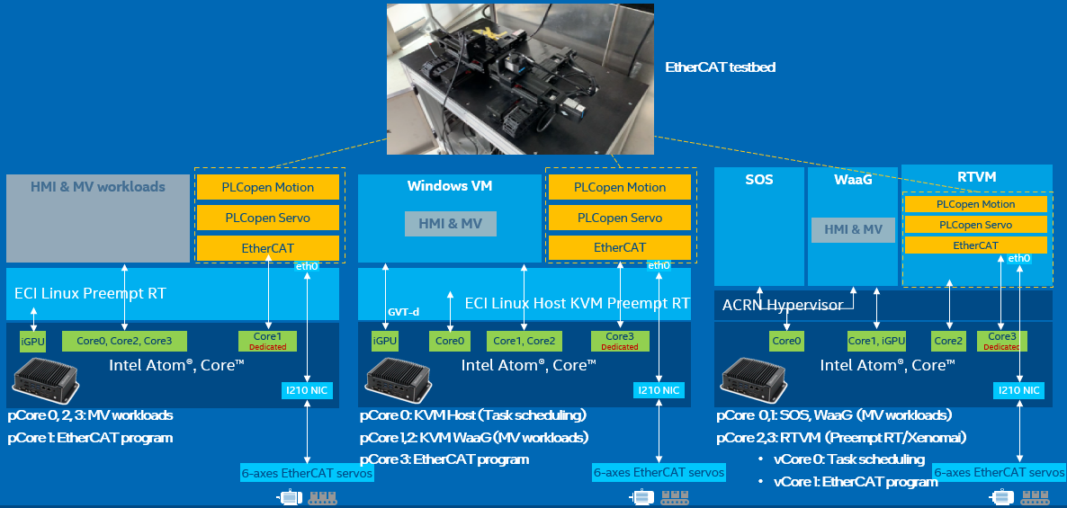
Figure 2. ECI motion configurations for Atom or Core CPU
As shown in the figure above, RTmotion can be set up to run with an Intel® Atom® or Intel® Core™ CPU in three configurations:
ECI-B (Bare-metal):
OS: Host (Preempt-RT/Xenomai)
One CPU core is isolated and dedicated for RTmotion real-time task.
Rest CPU cores and iGPU are used for non-real-time HMI/MV tasks.
ECI-K (KVM):
OS: Host (Preempt-RT), Guest VM (Microsoft Windows*)
One CPU core is isolated and dedicated for RTmotion real-time task.
One CPU core is used for host Linux* tasks.
Rest CPU cores and iGPU are used for Guest VM.
ECI-A (ACRN):
OS: Service OS (Linux*), Guest VM1 (Microsoft Windows*), Guest VM2 (Preempt-RT/Xenomai)
Two CPU cores are isolated and dedicated for Guest VM2. Among them, one is dedicated for RTmotion real-time task.
One CPU core is shared by Service OS and Guest VM1.
Rest CPU cores and iGPU are used for Guest VM1.
2.2. Configurations with hybrid cores#
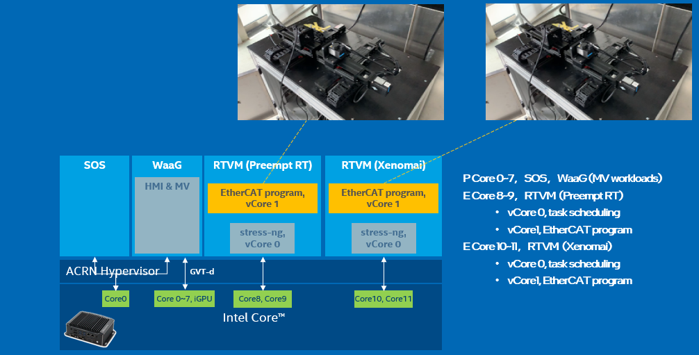
Figure 3. ECI motion configuration for hybrid CPU
The 12th generation of Intel® CPUs integrate Performance (P) and Efficient (E) cores. For example the ADL-S which has 8 P-core and 4 E-core. For best performance, real-time RTmotion tasks should run in a real-time VM running on an E-core. P-cores are used to run Microsoft Windows* VMs for non-real-time HMI/machine vision workloads. In this configuration, the P-core can support hyper-threading and hardware P-state features without sacrificing the real-time performance of the E-core:
OS: Service OS (Linux*), Guest VM1 (Microsoft Windows*), Guest VM2 (Preempt-RT/Xenomai), Guest VM3 (Preempt-RT/Xenomai)
Two E-core are dedicated for Guest VM2.
Two E-core are dedicated for Guest VM3.
One P-core is shared by Service OS and Guest VM1.
Rest P-core and iGPU are used for Guest VM1.
3. RTmotion Applications#
This section lists some of the RTmotion applications in the industrial automation domains. It shows how Intel® Edge Controls for Industrial with RTmotion enables customers to consolidate their real-time (motion control) and non-real-time (HMI/Machine Vision/CNC/ROS2 Robotics) workloads.
3.1. Logistics control#
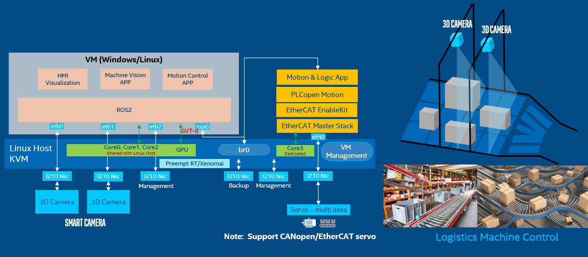
Figure 4. RTmotion application for parcel singulation controller
In this project, RTmotion enables customers to consolidate their machine vision and real-time motion control workloads to run on an Intel® x86 platform. This application scenario is very common in logistics. Parcel separation controllers typically consist of two separate systems: a PLC connected to the 28~84 conveyor EtherCAT servo motors for speed control, and a Microsoft Windows* IPC for parcel pose detection and servo motor speed planning. The results of the speed planning will be transmitted to the PLC via TCP/IP socket communication. As shown above, Intel® Edge Controls for Industrial solutions combine both functions into one platform. There will be an Intel® Edge Controls for Industrial Preempt RT Linux* OS running as the host. A CPU core is then isolated to run real-time RTmotion tasks to control servo motors, which in traditional solutions plays the role of a PLC. KVM is used here as the hypervisor to support running Microsoft Windows* guest VMs on Linux* hosts. Microsoft Windows* applications can be migrated to the guest VM without any modification.
3.2. SMT machine control with flying-trigger#
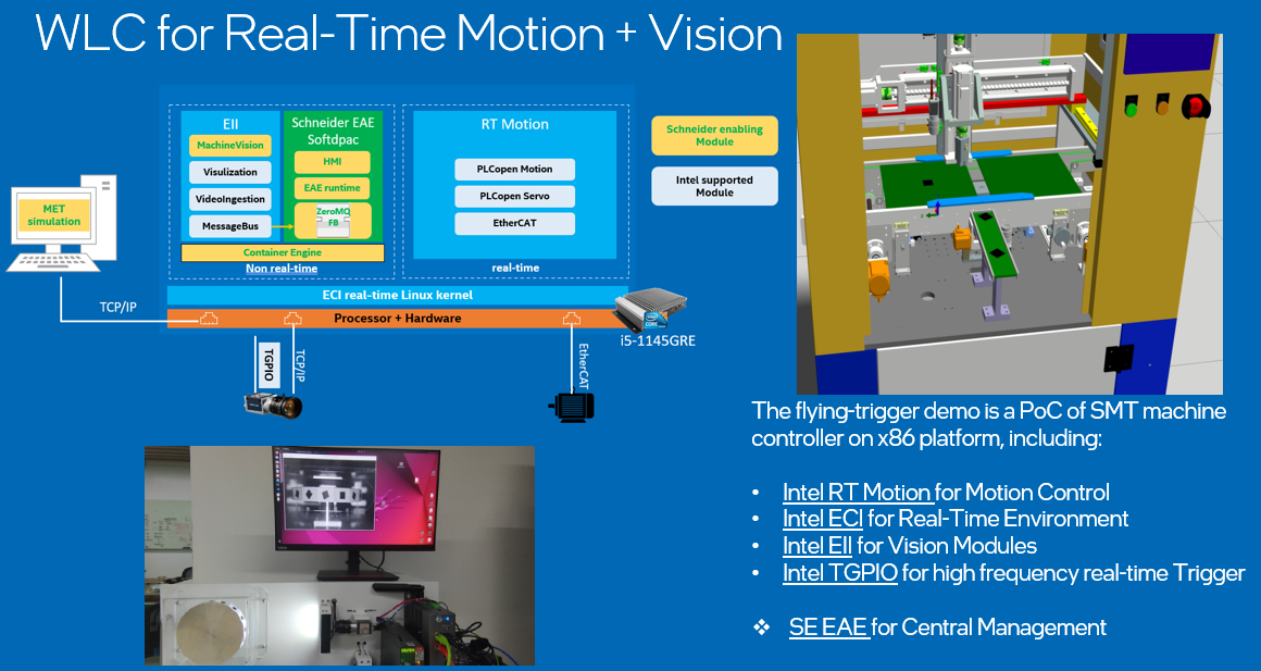
Figure 5. RTmotion application for flying-trigger
In this project, the RTmotion function block has been integrated into EcoStruxure* Automation Expert for motion control of SMT manufacturing. The project also integrated Intel® Edge Controls for Industrial flying-trigger technique and Intel® Edge Insights for Industrial to improve vision capture and detection efficiency. The key components are listed here:
Intel® RTmotion for motion control
Intel® Edge Controls for Industrial for real-time environment and fieldbus
Intel® Edge Insights for Industrial for vision modules and message bus
Intel® TGPIO for high frequency real-time I/O trigger
EcoStruxure* Automation Expert for runtime, PLC programming and central management
3.3. 100-axis control with EcoStruxure* Automation Expert#

Figure 6. RTmotion application for multiple axis control
Coating, winding and stacking machines in Li-battery manufacturing often require real-time synchronization between hundreds of axes and multiple functions (CamIn, GearIn, velocity and torque control, etc.). Intel® Edge Controls for Industrial with RTmotion has demonstrated the capability to meet this requirements, that controlling 100 EtherCAT servo motors within 1ms cycle time with a maximum real-time latency of 15us. The RTmotion is also integrated in EcoStruxure* Automation Expert in this project.
3.4. AMR control#
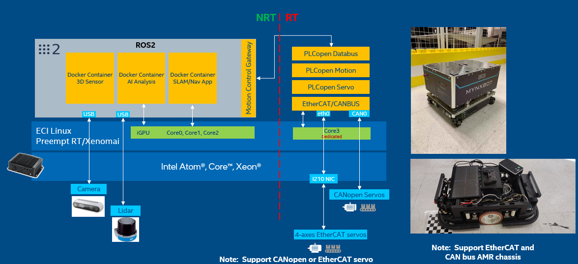
Figure 7. RTmotion application for AMR control
AMR (Autonomous Mobile Robot) is now widely used in warehouses, logistical companies, agriculture businesses, and healthcare institutions. AMR typically consists of two independent hardware control systems: one for real-time motion control and another for SLAM/path planning/vision. Since AMR usually only needs to drive less than 4 servo motors with low accuracy velocity control, and the kinematics and dynamics model for the whole-body control are simpler compared to that of a 6-axis robot arm, the low-end computing unit is sufficient to complete the real-time motion control. With Intel® Edge Controls for Industrial and RTmotion, it is quite reasonable and easy to integrate two independent systems, from which customers can benefit from reduced hardware costs, higher reliability, system flexibility and easy upgrades. As shown in the figure above, one CPU core can be isolated to run RTmotion tasks to drive mobile platforms. Both CANopen and EtherCAT based servo motors are supported. ROS2 tasks can utilize remaining CPU and system resources to implement SLAM/path planning/vision functions. Buttons, safety sensors and other I/O devices can be easily controlled via remote IO modules based on CANBus, EtherCAT or Modbus.
3.5. Robot arm control#
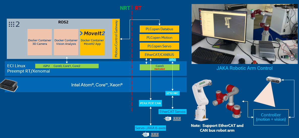
Figure 8. RTmotion application for robot arm control
Similar to the concept of AMR, the robotic arm control workloads can also be consolidated by Intel® Edge Controls for Industrial with RTmotion. With the development of machine vision, AI and advanced motion planning technique, new type of intelligent robot arm controllers have been widely used. However, this intelligent controller is often separated from the robot arm’s native controller, which is only responsible for real-time motion control. This increases the difficulty of system adaptation. At the same time, in recent years, there has been a trend in the industry to consolidate PLC control, real-time motion control of robotic arms, machine vision and HMI into one controller to support the overall development of automated workstations.
3.6. Inspection machine control#
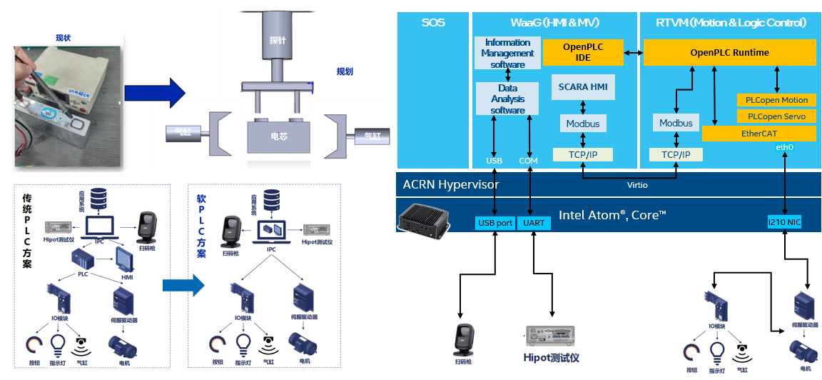
Figure 9. RTmotion application for inspection machine
Patches provided by Intel® Edge Controls for Industrial have integrated RTmotion into the IDE and runtime of Open Source SoftPLC (OpenPLC). Customers can do IEC 61131-3 PLC programming for motion control as they normally do on traditional PLC products. Through the RTmotion configuration introduced in Chapter 2, customers can customize the PC-based SoftPLC controller according to their needs. Since most non-standard automation equipment only requires PTP movement, RTmotion’s function blocks MC_MoveAbsolute, MC_Homing, and MC_MoveRelative can meet these usage scenarios. As shown in the figure above, the customer migrated all the functions of the PLC in the Li-battery Hipot test device to the PC-based soft PLC controller through Intel® Edge Controls for Industrial and RTmotion. This helps customers reduce hardware costs and makes the entire system IT-friendly.
4. RTmotion Function Blocks#
This section will introduce the usage interface and function diagram of each function block.
4.1. MC_Stop#
MC_STOP cannot be aborted by another FB. An error could happen when another motion FB is triggered on the same axis before MC_STOP finish its task.
4.1.1. MC_STOP inputs/outputs#
FB-Name |
MC_STOP |
|
|---|---|---|
VAR_IN_OUT |
||
Axis |
AXIS_REF |
Reference to the axis |
VAR_INPUT |
||
Execute |
BOOL |
Start the action at rising edge |
Deceleration |
LREAL |
Value of the Deceleration |
Jerk |
LREAL |
Value of the Jerk |
VAR_OUTPUT |
||
Done |
BOOL |
Zero velocity reached |
Busy |
BOOL |
The FB is not finished and new output values are to be expected |
CommandAborted |
BOOL |
Command is aborted |
Error |
BOOL |
Signals that an error has occurred within the Function Block |
ErrorID |
MC_ERROR_CODE |
Error identification |
4.1.2. MC_STOP diagram#
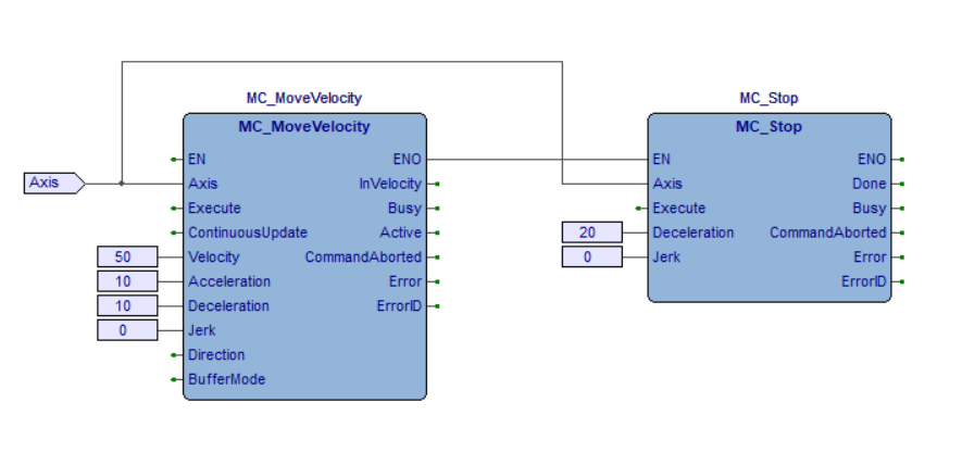
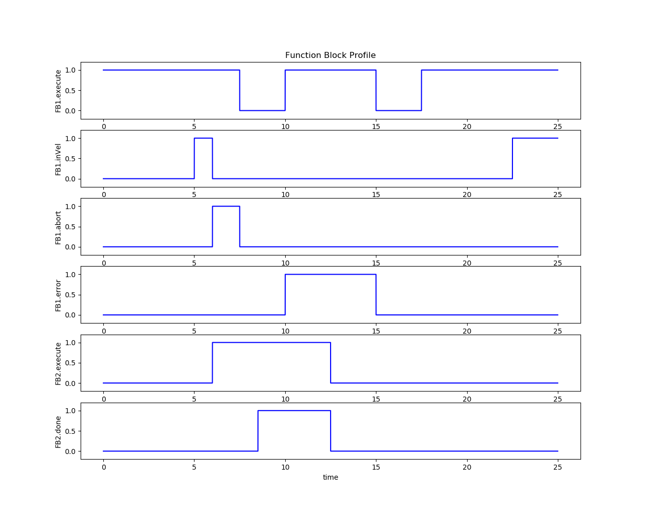
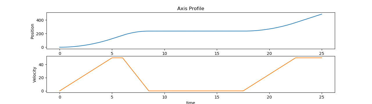
Figure 10. Time series plot for the MC_Stop execution results
4.2. MC_Halt#
MC_Halt can be aborted by another FB even if the velocity of axis has not been decelerated to zero.
4.2.1. MC_Halt inputs/outputs#
FB-Name |
MC_Halt |
|
|---|---|---|
VAR_IN_OUT |
||
Axis |
AXIS_REF |
Reference to the axis |
VAR_INPUT |
||
Execute |
BOOL |
Start the action at rising edge |
Deceleration |
LREAL |
Value of the Deceleration |
Jerk |
LREAL |
Value of the Jerk |
BufferMode |
MC_BUFFER_MODE |
Defines the chronological sequence of the FB |
VAR_OUTPUT |
||
Done |
BOOL |
Zero velocity reached |
Busy |
BOOL |
The FB is not finished and new output values are to be expected |
Active |
BOOL |
Indicates that the FB has control on the axis |
CommandAborted |
BOOL |
Command is aborted |
Error |
BOOL |
Signals that an error has occurred within the Function Block |
ErrorID |
MC_ERROR_CODE |
Error identification |
4.2.2. MC_Halt diagram#
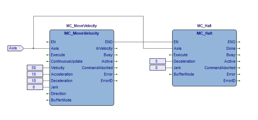
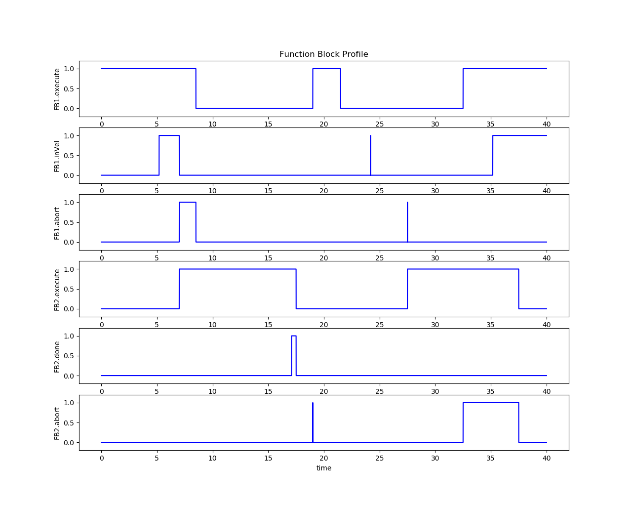
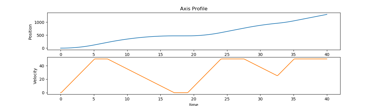
Figure 11. Time series plot for the MC_Halt execution results
4.3. MC_MoveAbsolute#
This Function Block commands a controlled motion to a specified absolute position.
4.3.1. MC_MoveAbsolute inputs/outputs#
FB-Name |
MC_MoveAbsolute |
|
|---|---|---|
VAR_IN_OUT |
||
Axis |
AXIS_REF |
Reference to the axis |
VAR_INPUT |
||
Execute |
BOOL |
Start the action at rising edge |
Position |
LREAL |
Target absolute position |
Velocity |
LREAL |
Maximum velocity |
Acceleration |
LREAL |
Maximum acceleration |
Deceleration |
LREAL |
Maximum deceleration |
Jerk |
LREAL |
Maximum jerk |
Direction |
MC_DIRECTION |
Enum type not used (Set through MC_Power) |
BufferMode |
MC_BUFFER_MODE |
Defines the chronological sequence of the FB |
VAR_OUTPUT |
||
Done |
BOOL |
Commanded distance reached |
Busy |
BOOL |
The FB is not finished and new output values are to be expected |
Active |
BOOL |
Indicates that the FB has control on the axis |
CommandAborted |
BOOL |
Command is aborted |
Error |
BOOL |
Signals that an error has occurred within the Function Block |
ErrorID |
MC_ERROR_CODE |
Error identification |
4.3.2. MC_MoveAbsolute diagram#
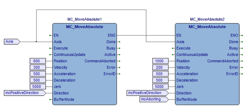


Figure 12. Time series plot for the MC_MoveAbsolute execution results
4.4. MC_MoveRelative#
This Function Block commands a controlled motion of a specified distance relative to the set position at the time of the execution.
4.4.1. MC_MoveRelative inputs/outputs#
FB-Name |
MC_MoveRelative |
|
|---|---|---|
VAR_IN_OUT |
||
Axis |
AXIS_REF |
Reference to the axis |
VAR_INPUT |
||
Execute |
BOOL |
Start the action at rising edge |
Distance |
LREAL |
Relative distance of the motion |
Velocity |
LREAL |
Maximum velocity |
Acceleration |
LREAL |
Maximum acceleration |
Deceleration |
LREAL |
Maximum deceleration |
Jerk |
LREAL |
Maximum jerk |
BufferMode |
MC_BUFFER_MODE |
Defines the chronological sequence of the FB |
VAR_OUTPUT |
||
Done |
BOOL |
Commanded distance reached |
Busy |
BOOL |
The FB is not finished and new output values are to be expected |
Active |
BOOL |
Indicates that the FB has control on the axis |
CommandAborted |
BOOL |
Command is aborted |
Error |
BOOL |
Signals that an error has occurred within the Function Block |
ErrorID |
MC_ERROR_CODE |
Error identification |
4.4.2. MC_MoveRelative diagram#
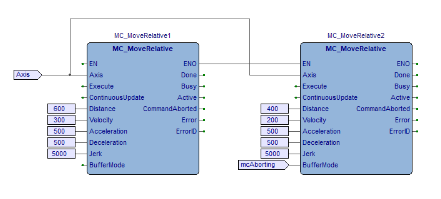
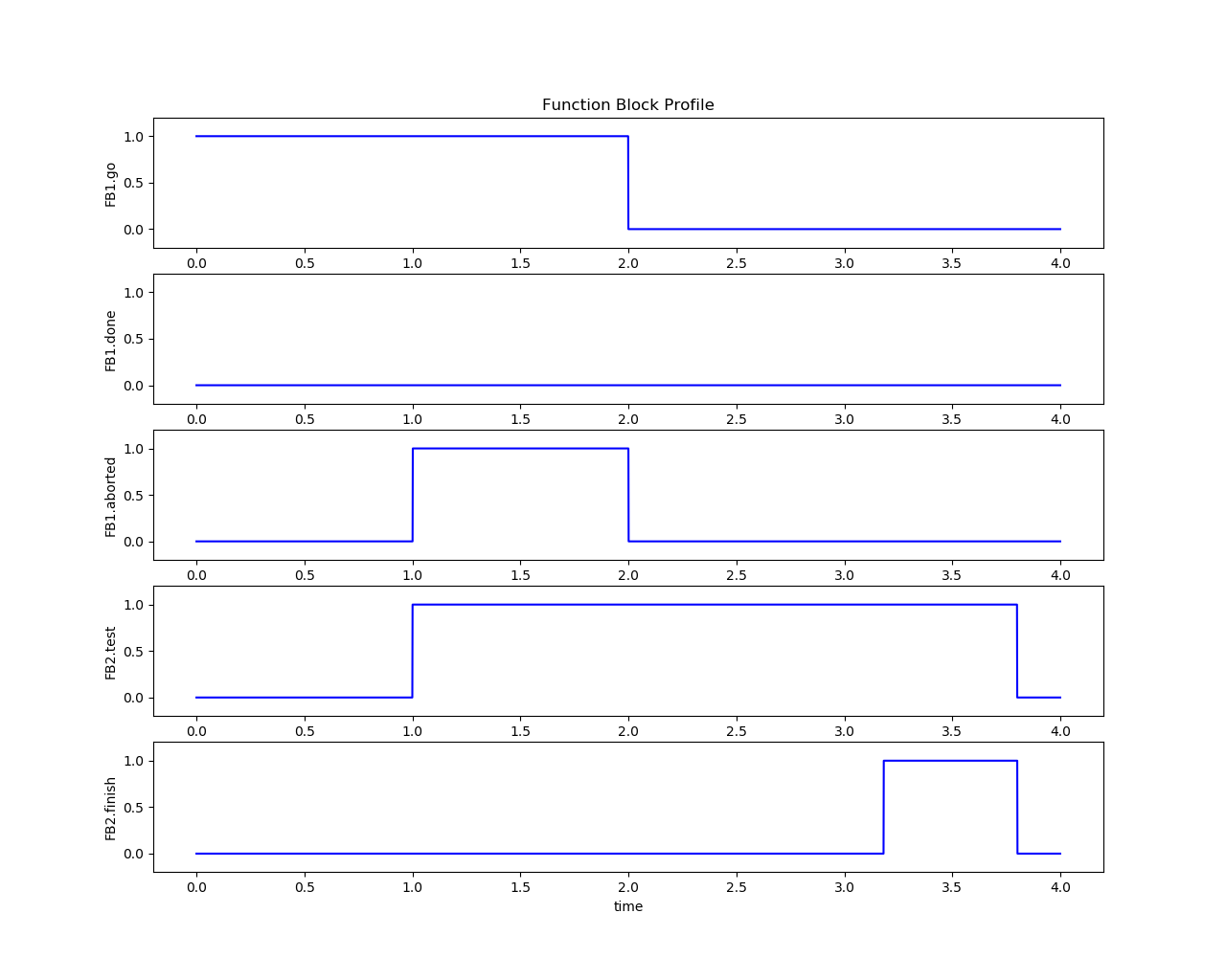
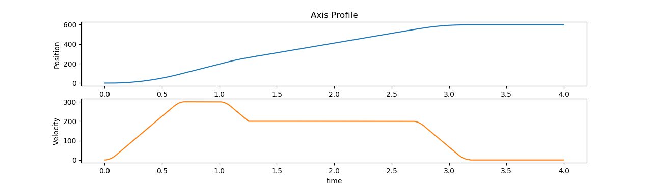
Figure 13. Time series plot for the MC_MoveRelative execution results
4.5. MC_MoveAdditive#
This Function Block commands a controlled motion of a specified relative distance additional to the most recent commanded position in the axis state DiscreteMotion. The most recent commanded position may be the result of a previous MC_MoveAdditive motion which was aborted. If the FB is activated in the axis state ContinuousMotion, the specified relative distance is added to the set position at the time of the execution.
4.5.1. MC_MoveAdditive inputs/outputs#
FB-Name |
MC_MoveAdditive |
|
|---|---|---|
VAR_IN_OUT |
||
Axis |
AXIS_REF |
Reference to the axis |
VAR_INPUT |
||
Execute |
BOOL |
Start the action at rising edge |
Distance |
LREAL |
Relative distance of the motion |
Velocity |
LREAL |
Maximum velocity |
Acceleration |
LREAL |
Maximum acceleration |
Deceleration |
LREAL |
Maximum deceleration |
Jerk |
LREAL |
Maximum jerk |
BufferMode |
MC_BUFFER_MODE |
Defines the chronological sequence of the FB |
VAR_OUTPUT |
||
Done |
BOOL |
Commanded distance reached |
Busy |
BOOL |
The FB is not finished and new output values are to be expected |
Active |
BOOL |
Indicates that the FB has control on the axis |
CommandAborted |
BOOL |
Command is aborted |
Error |
BOOL |
Signals that an error has occurred within the Function Block |
ErrorID |
MC_ERROR_CODE |
Error identification |
4.5.2. MC_MoveAdditive diagram#
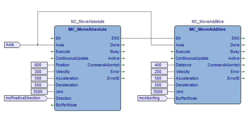
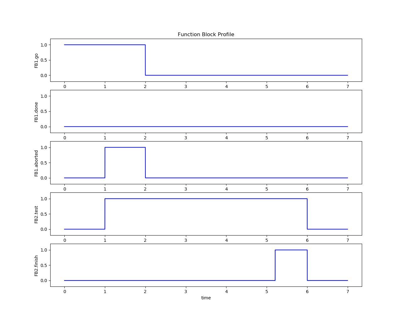
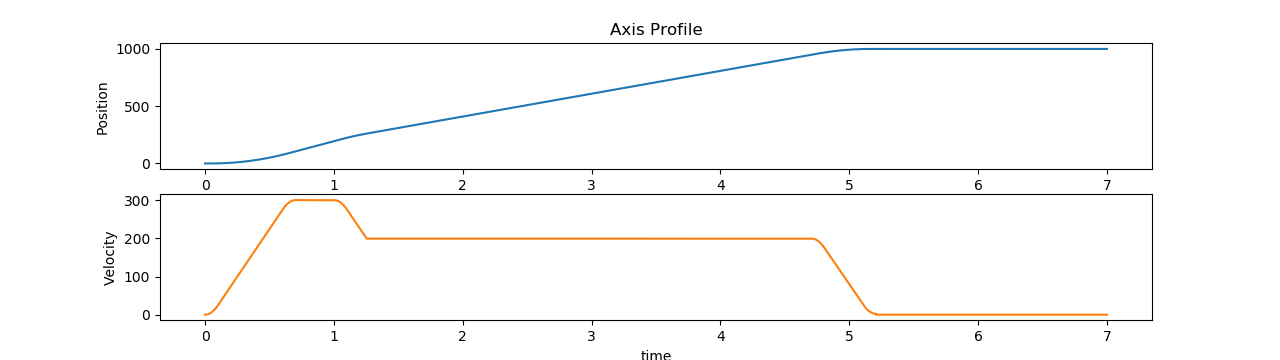
Figure 14. Time series plot for the MC_MoveAdditive execution results
4.6. MC_MoveSuperimposed#
This Function Block Commands a controlled motion of a specified relative distance additional to an existing motion. The existing Motion is not interrupted, but is superimposed by the additional motion.
Behavior when active:
If MC_MoveSuperimposed is active, then any other command in aborting mode except MC_MoveSuperimposed will abort both motion commands: both the MC_MoveSuperimposed and the underlying motion command.
If MC_MoveSuperimposed is active and another MC_MoveSuperimposed is commanded, only the on-going MC_MoveSuperimposed command is aborted, and replaced by the new MC_MoveSuperimposed, but not the underlying motion command.
If MC_MoveSuperimposed is active, then any new added FB will abort underlying and on-going superimposed motion.
In the state ‘Standstill’ the FB MC_MoveSuperimposed acts like MC_MoveRelative.
4.6.1. MC_MoveSuperimposed inputs/outputs#
FB-Name |
MC_MoveSuperimposed |
|
|---|---|---|
VAR_IN_OUT |
||
Axis |
AXIS_REF |
Reference to the axis |
VAR_INPUT |
||
Execute |
BOOL |
Start the action at rising edge |
Distance |
LREAL |
Additional distance that is to be superimposed |
VelocityDiff |
LREAL |
Value of the velocity difference of the additional motion |
Acceleration |
LREAL |
Value of the Acceleration |
Deceleration |
LREAL |
Value of the Deceleration |
Jerk |
LREAL |
Value of the Jerk |
VAR_OUTPUT |
||
Done |
BOOL |
Additional distance superimposed to the ongoing motion |
Busy |
BOOL |
The FB is not finished and new output values are to be expected |
CommandAborted |
BOOL |
Command is aborted |
Error |
BOOL |
Signals that an error has occurred within the Function Block |
ErrorID |
MC_ERROR_CODE |
Error identification |
CoveredDistance |
LREAL |
Displays continuously the covered distance contributed by this FB since it was started |
4.6.2. MC_MoveSuperimposed diagram#
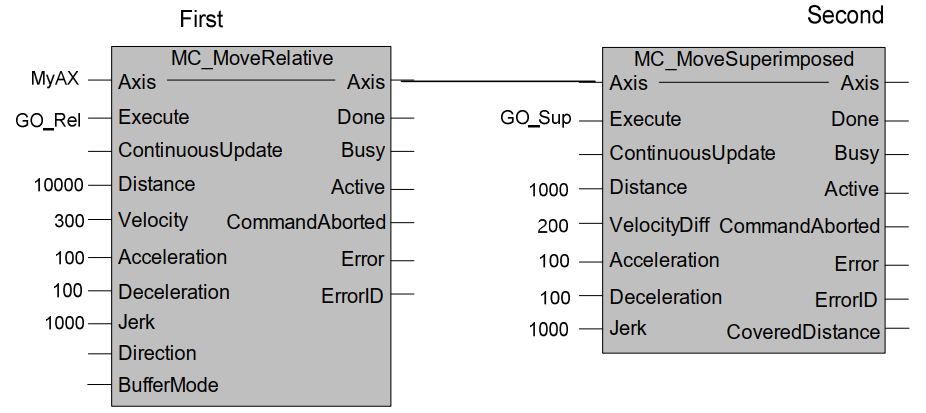
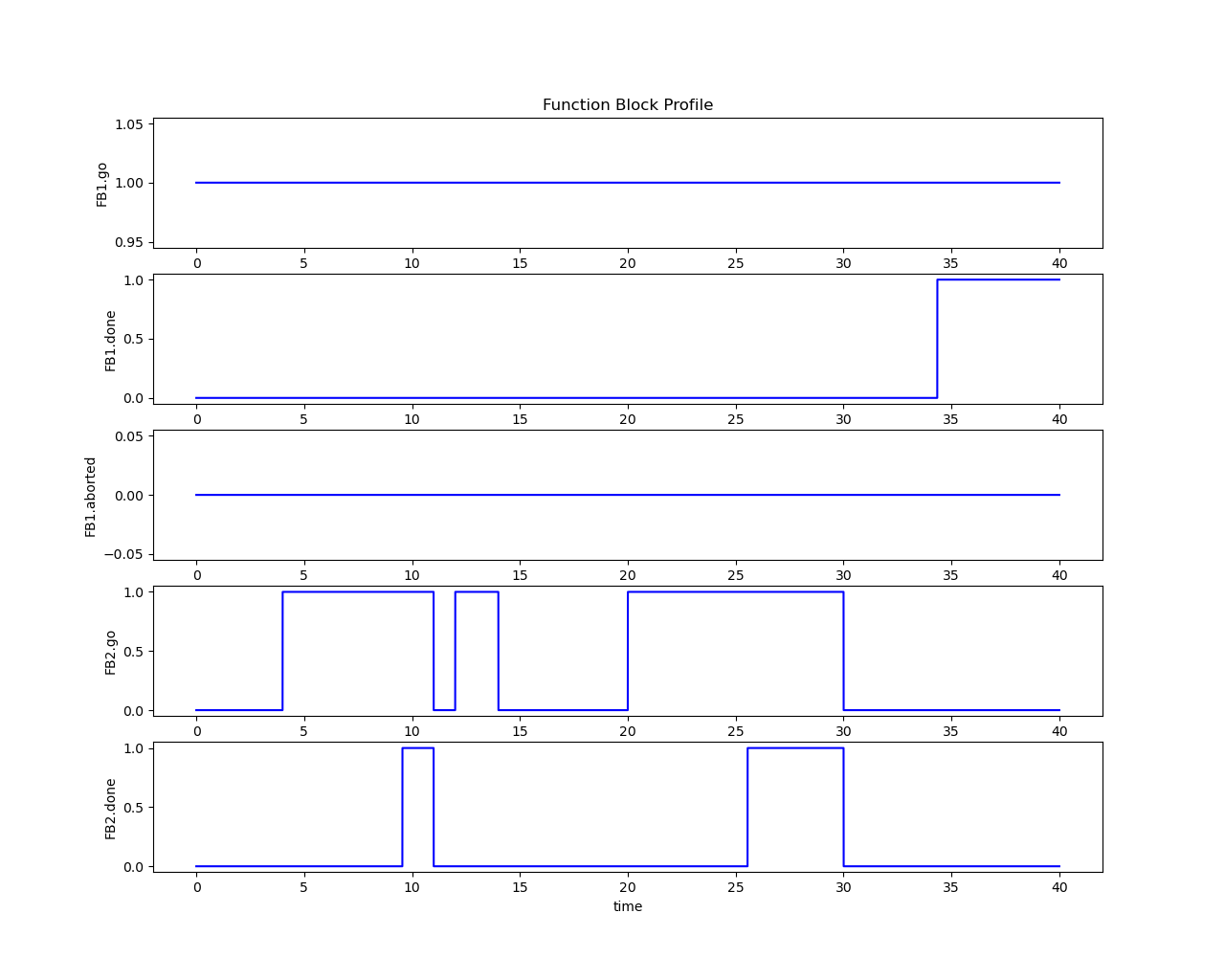
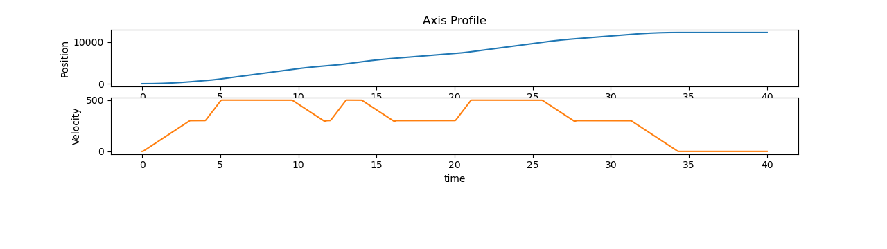
Figure 15. Time series plot for the MC_MoveSuperimposed execution results
4.7. MC_MoveVelocity#
This Function Block commands a never ending controlled motion at a specified velocity.
4.7.1. MC_MoveVelocity inputs/outputs#
FB-Name |
MC_MoveVelocity |
|
|---|---|---|
VAR_IN_OUT |
||
Axis |
AXIS_REF |
Reference to the axis |
VAR_INPUT |
||
Execute |
BOOL |
Start the action at rising edge |
Velocity |
LREAL |
Target velocity to reach |
Acceleration |
LREAL |
Maximum acceleration |
Deceleration |
LREAL |
Maximum deceleration |
Jerk |
LREAL |
Maximum jerk |
Direction |
MC_DIRECTION |
Not used (set through MC_Power) |
BufferMode |
MC_BUFFER_MODE |
Defines the chronological sequence of the FB |
VAR_OUTPUT |
||
InVelocity |
BOOL |
Commanded velocity reached |
Busy |
BOOL |
The FB is not finished and new output values are to be expected |
Active |
BOOL |
Indicates that the FB has control on the axis |
CommandAborted |
BOOL |
Command is aborted |
Error |
BOOL |
Signals that an error has occurred within the Function Block |
ErrorID |
MC_ERROR_CODE |
Error identification |
4.7.2. MC_MoveVelocity diagram#
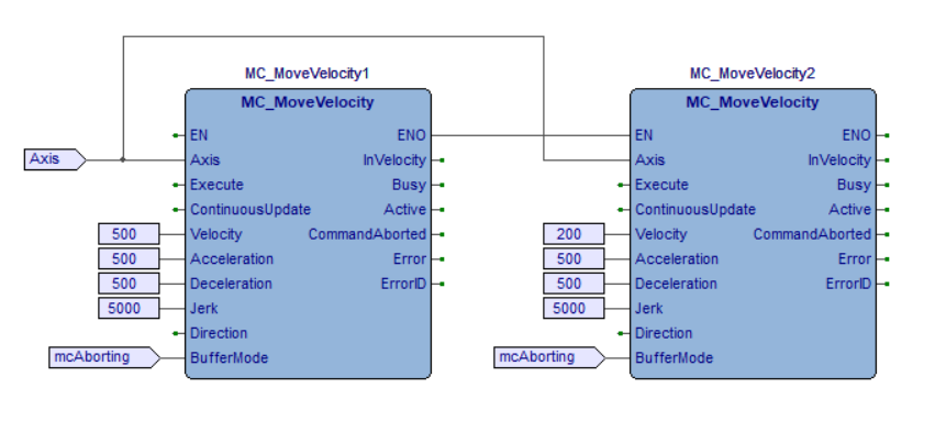
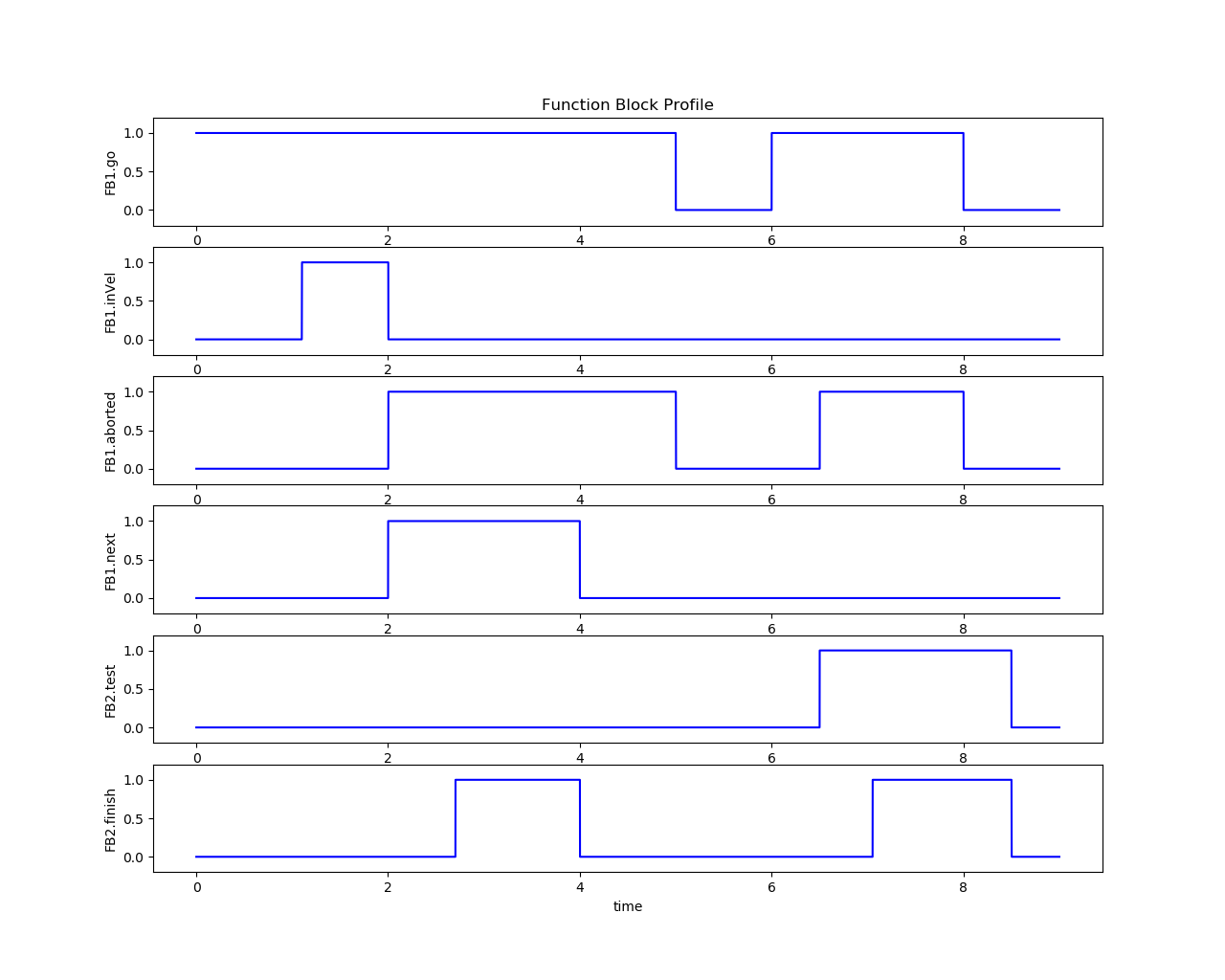
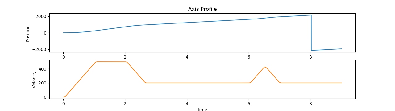
Figure 16. Time series plot for the MC_MoveVelocity execution results
4.8. MC_Homing#
This Function Block commands the axis to perform the ‘search home’ sequence. The details of this sequence are manufacturer dependent. RTmotion MC_Homing FB takes the current position as the home position when comes across the rising edge of AbsoluteSwitchSignal in the search direction or the falling edge of the signal in the diverse direction. Since the velocity can not be decelerated to zero when the absolute signal is triggered, this function block will decelerate and return back to stop at the home position.
4.8.1. MC_Homing inputs/outputs#
FB-Name |
MC_Homing |
|
|---|---|---|
VAR_IN_OUT |
||
Axis |
AXIS_REF |
Reference to the axis |
VAR_INPUT |
||
Execute |
BOOL |
Start the action at rising edge |
Direction |
MC_DIRECTION |
The direction to move when the homing is started |
AbsoluteSwitchSignal |
BOOL |
The signal to indicate the home position is reached |
LimitSwitchNegativeSignal |
BOOL |
The signal to indicate the negative limit position is reached |
LimitSwitchPositiveSignal |
BOOL |
The signal to indicate the positive limit position is reached |
LimitOffset |
LREAL |
The safety distance that needs to stop away from the limit position |
Velocity |
LREAL |
Maximum velocity |
Acceleration |
LREAL |
Maximum acceleration |
Deceleration |
LREAL |
Maximum deceleration (same to acceleration) |
Jerk |
LREAL |
Maximum jerk |
VAR_OUTPUT |
||
Done |
BOOL |
Axis stops at the home position |
Busy |
BOOL |
The FB is not finished and new output values are to be expected |
Active |
BOOL |
Indicates that the FB has control on the axis |
CommandAborted |
BOOL |
Command is aborted |
Error |
BOOL |
Signals that an error has occurred within the Function Block |
ErrorID |
MC_ERROR_CODE |
Error identification |
4.8.2. MC_Homing diagram#
The small white squares stand for the position that axis starts the homing process.
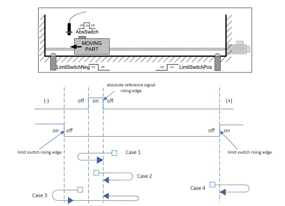
Figure 17. PLC homing cases
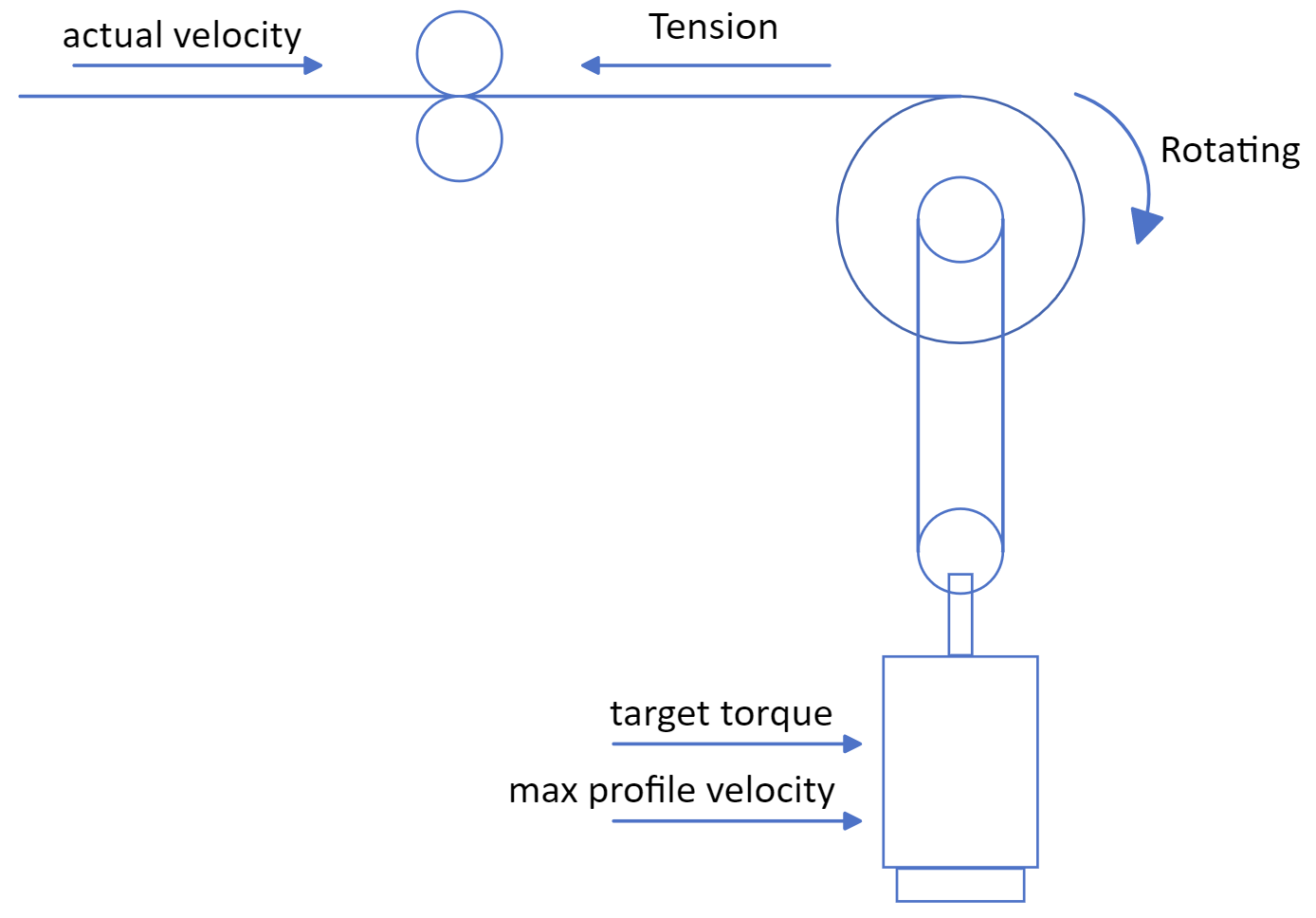
4.9. MC_TorqueControl#
The FB activates the CST (cyclic synchronous torque) mode. In the CST mode, the motion is executed with a target torque. The reference value for the target torque is provided by input Torque. After the target torque is reached, the output InTorque is set to TRUE.
4.9.1. MC_TorqueControl inputs/outputs#
FB-Name |
MC_TorqueControl |
|
|---|---|---|
VAR_IN_OUT |
||
Axis |
AXIS_REF |
Reference to the axis |
VAR_INPUT |
||
Execute |
BOOL |
Starts the motion on a rising edge |
Torque |
BOOL |
Value of the torque. (Torque or force in technical unit [u]) |
MaxProfileVelocity |
BOOL |
Absolute value of the maximum profile velocity |
BufferMode |
BOOL |
Defines the chronological sequence of the FB |
VAR_OUTPUT |
||
InTorque |
BOOL |
Setpoint value of torque or force equals the commanded value |
Busy |
BOOL |
The FB is not finished and new output values are to be expected |
Error |
BOOL |
Signals that an error has occurred within the Function Block |
ErrorID |
MC_ERROR_CODE |
Error identification |
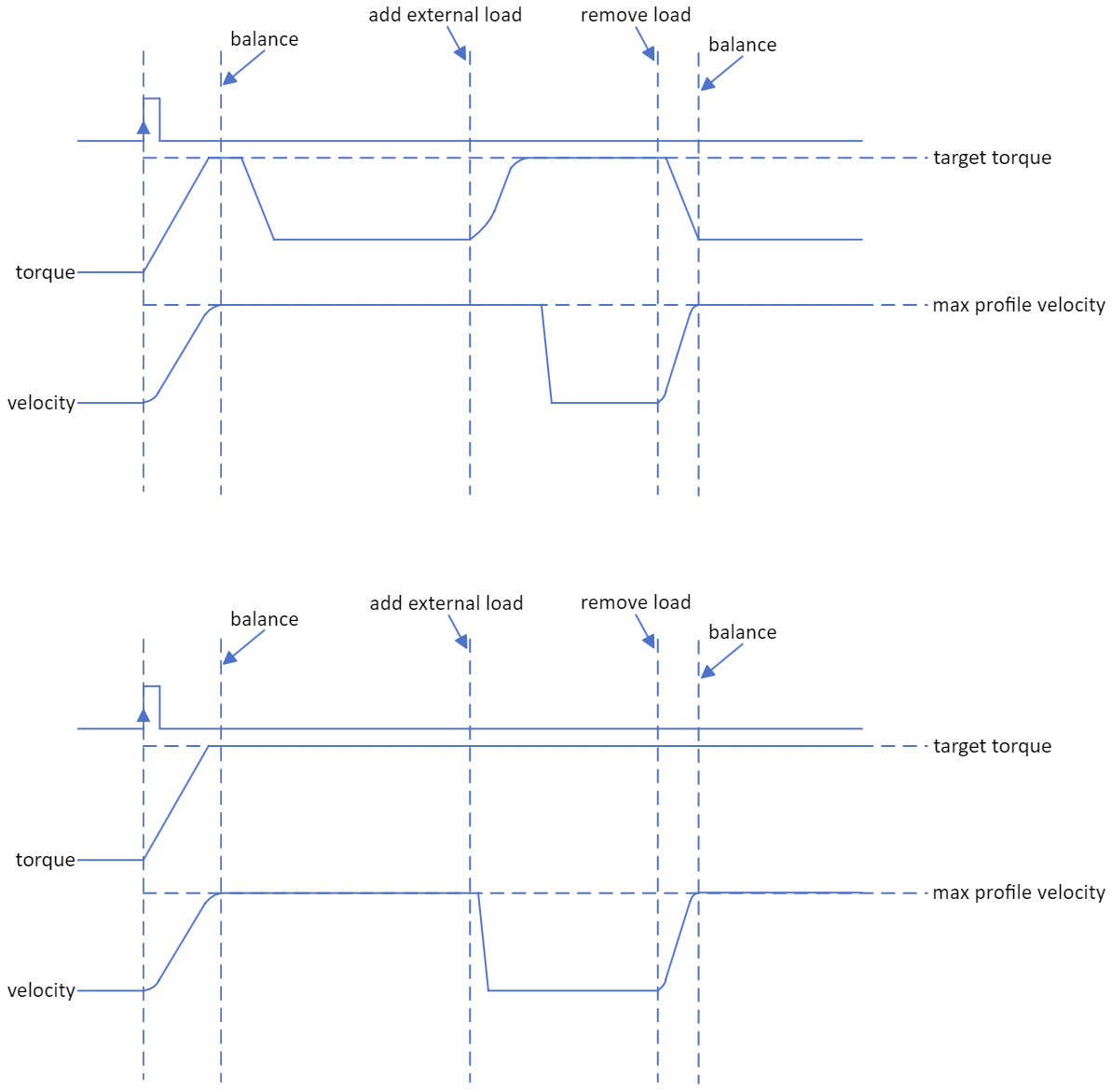
4.9.2. MC_TorqueControl diagram#
The value of max profile velocity default set by servo API or via the axis parameter table.
4.10. MC_Home#
This Function Block commands drive to search the home reference signal with the homing-specific settings of the drive.
4.10.1. MC_Home#
FB-Name |
MC_Home |
|
|---|---|---|
VAR_IN_OUT |
||
Axis |
AXIS_REF |
Reference to the axis |
VAR_INPUT |
||
Execute |
BOOL |
Start the homing at the rising edge |
VAR_OUTPUT |
||
Done |
BOOL |
Drive homing completed |
Busy |
BOOL |
The FB is not finished and new output values are to be expected |
CommandAborted |
BOOL |
Command is aborted |
Error |
BOOL |
Signals that an error has occurred within the Function Block |
ErrorID |
MC_ERROR_CODE |
Error identification |
4.10.2. MC_Home drive parameters setting#
Refer to the user guide of the drive for the Homing-specific parameter settings. These parameters can be set by servo SDO or via the axis parameter table.
Homing method: selects the homing method.Homing speeds: sets the two speeds used in homing procedure, one for speed during search for switch and other for speed during search for zero.
4.11. MC_Jog#
This Function Block commands a jogged movement to an axis as long as the input JogForward or JogBackward is set.
4.11.1. MC_Jog#
FB-Name |
MC_Jog |
|
|---|---|---|
VAR_IN_OUT |
||
Axis |
AXIS_REF |
Reference to the axis |
VAR_INPUT |
||
JogForward |
BOOL |
Start the jogged motion in positive direction |
JogBackward |
BOOL |
Start the jogged motion in negative direction |
Velocity |
REAL |
Maximum velocity |
Acceleration |
REAL |
Maximum acceleration |
Deceleration |
REAL |
Maximum deceleration |
Jerk |
REAL |
Maximum jerk |
VAR_OUTPUT |
||
Done |
BOOL |
Jogged movement completed |
Busy |
BOOL |
The FB is not finished and new output values are to be expected |
CommandAborted |
BOOL |
Command is aborted |
Error |
BOOL |
Signals that an error has occurred within the Function Block |
ErrorID |
MC_ERROR_CODE |
Error identification |
4.11.2. MC_Jog Diagram#
4.12. MC_Power#
This Function Block controls the power stage (On or Off). The power-on process depends on the fieldbus protocol content. For example, if RTmotion is connected to a CiA402 EtherCAT servo motor, the power-on process switches the servo motor state to “Operation Enabled” state. It also resolves situations where state switching encounters errors or exceptions, or the servo motor reports an error when an electrical or physical condition occurs.
4.12.1. MC_Power inputs/outputs#
FB-Name |
MC_Power |
|
|---|---|---|
VAR_IN_OUT |
||
Axis |
AXIS_REF |
Reference to the axis |
VAR_INPUT |
||
Enable |
BOOL |
As long as ‘Enable’ is true, power is being enabled |
EnablePositive |
BOOL |
As long as ‘Enable’ is true, this permits motion in positive direction |
EnableNegative |
BOOL |
As long as ‘Enable’ is true, this permits motion in negative direction |
VAR_OUTPUT |
||
status |
BOOL |
Effective state of the power stage |
Valid |
BOOL |
If true, a valid set of outputs is available at the FB |
Error |
BOOL |
Signals that an error has occurred within the Function Block |
ErrorID |
MC_ERROR_CODE |
Error identification |
4.13. MC_Reset#
This Function Block makes the transition from the state ‘ErrorStop’ to ‘Standstill’ or ‘Disabled’ by resetting all internal axis-related errors - it does not affect the output of the FB instances.
4.13.1. MC_Reset inputs/outputs#
FB-Name |
MC_Reset |
|
|---|---|---|
VAR_IN_OUT |
||
Axis |
AXIS_REF |
Reference to the axis |
VAR_INPUT |
||
Execute |
BOOL |
Resets all internal axis-related errors |
VAR_OUTPUT |
||
Done |
BOOL |
‘Standstill’ or ‘Disabled’ state is reached |
Busy |
BOOL |
The FB is not finished and new output values are to be expected |
Error |
BOOL |
Signals that an error has occurred within the Function Block |
ErrorID |
MC_ERROR_CODE |
Error identification |
4.14. MC_SetPosition#
This Function Block shifts the coordinate system of an axis by manipulating both the set-point position as well as the actual position of an axis with the same value without any movement caused. (Re-calibration with same following error). This can be used for instance for a reference situation. This Function Block can also be used during motion without changing the commanded position, which is now positioned in the shifted coordinate system.
4.14.1. MC_SetPosition inputs/outputs#
FB-Name |
MC_SetPosition |
|
|---|---|---|
VAR_IN_OUT |
||
Axis |
AXIS_REF |
Reference to the axis |
VAR_INPUT |
||
Execute |
BOOL |
Start setting position in axis |
Position |
LREAL |
Shifts coordinates with current position as input ‘Position’ |
Mode |
MC_SET_POSITION_MODE |
‘mcSetPositionModeRelative’ or ‘mcSetPositionModeAbsolute’ |
VAR_OUTPUT |
||
Done |
BOOL |
Axis coordinates shift finished |
Busy |
BOOL |
The FB is not finished and new output values are to be expected |
Error |
BOOL |
Signals that an error has occurred within the Function Block |
ErrorID |
MC_ERROR_CODE |
Error identification |
mcSetPositionModeRelative: means that ‘Position’ is added to the actual position value of the axis at the time of execution. This results in a re-calibration by a specified distance.mcSetPositionModeAbsolute: means that the actual position value of the axis is set to the value specified in the ‘Position’ parameter.
4.15. MC_ReadStatus#
This Function Block returns in detail the status of the state diagram of the selected axis.
4.15.1. MC_ReadStatus inputs/outputs#
FB-Name |
MC_ReadStatus |
|
|---|---|---|
VAR_IN_OUT |
||
Axis |
AXIS_REF |
Reference to the axis |
VAR_INPUT |
||
Enable |
BOOL |
Get the value of the parameter continuously while enabled |
VAR_OUTPUT |
||
Valid |
BOOL |
A valid set of outputs is available at the FB |
Busy |
BOOL |
The FB is not finished and new output values are to be expected |
Error |
BOOL |
Signals that an error has occurred within the Function Block |
ErrorID |
MC_ERROR_CODE |
Error identification |
ErrorStop |
BOOL |
Axis state in state diagram |
Disabled |
BOOL |
Axis state in state diagram |
Stopping |
BOOL |
Axis state in state diagram |
Homing |
BOOL |
Axis state in state diagram |
Standstill |
BOOL |
Axis state in state diagram |
DiscreteMotion |
BOOL |
Axis state in state diagram |
ContinuousMotion |
BOOL |
Axis state in state diagram |
SynchronizedMotion |
BOOL |
Axis state in state diagram |
4.16. MC_ReadAxisInfo#
This Function Block reads information concerning an axis, like modes, inputs directly related to the axis, and certain status information.
4.16.1. MC_ReadAxisInfo inputs/outputs#
FB-Name |
MC_ReadAxisInfo |
|
|---|---|---|
VAR_IN_OUT |
||
Axis |
AXIS_REF |
Reference to the axis |
VAR_INPUT |
||
Enable |
BOOL |
Get the value of the parameter continuously while enabled |
VAR_OUTPUT |
||
Valid |
BOOL |
A valid set of outputs is available at the FB |
Busy |
BOOL |
The FB is not finished and new output values are to be expected |
Error |
BOOL |
Signals that an error has occurred within the Function Block |
ErrorID |
MC_ERROR_CODE |
Error identification |
HomeAbsSwitch |
BOOL |
Digital home switch input is active |
LimitSwitchPos |
BOOL |
Positive hardware end switch is active |
LimitSwitchNeg |
BOOL |
Negative hardware end switch is active |
Simulation |
BOOL |
Axis is in simulation mode |
CommunicationReady |
BOOL |
Network is initialized and ready for communication |
ReadyForPowerOn |
BOOL |
Drive is ready to be enabled |
PowerOn |
BOOL |
If TRUE shows that the power stage is switched ON |
IsHomed |
BOOL |
The absolute reference position is known for the axis |
AxisWarning |
BOOL |
Warning(s) on the axis is present |
4.17. MC_ReadAxisError#
This Function Block presents general axis errors not relating to the Function Blocks. (for instance axis errors, drive errors, communication errors)
4.17.1. MC_ReadAxisError inputs/outputs#
FB-Name |
MC_ReadAxisError |
|
|---|---|---|
VAR_IN_OUT |
||
Axis |
AXIS_REF |
Reference to the axis |
VAR_INPUT |
||
Enable |
BOOL |
Get the value of the parameter continuously while enabled |
VAR_OUTPUT |
||
Valid |
BOOL |
A valid set of outputs is available at the FB |
Busy |
BOOL |
The FB is not finished and new output values are to be expected |
AxisErrorID |
MC_ERROR_CODE |
The value of the axis error. Vendor specific. |
4.18. MC_ReadCommandPosition#
The FB reads the motion command returned from the motion kernel to the axis, which is used to update to the servo motor in the current thread cycle.
4.18.1. MC_ReadCommandPosition inputs/outputs#
FB-Name |
MC_ReadCommandPosition |
|
|---|---|---|
VAR_IN_OUT |
||
Axis |
AXIS_REF |
Reference to the axis |
VAR_INPUT |
||
Enable |
BOOL |
Get the value of the parameter continuously while enabled |
VAR_OUTPUT |
||
Valid |
BOOL |
A valid set of outputs is available at the FB |
Busy |
BOOL |
The FB is not finished and new output values are to be expected |
Error |
BOOL |
Signals that an error has occurred within the Function Block |
ErrorID |
MC_ERROR_CODE |
Error identification |
Position |
LREAL |
The commanded position to the servo |
4.19. MC_ReadCommandVelocity#
The FB reads the motion command returned from the motion kernel to the axis, which is used to update to the servo motor in the current thread cycle.
4.19.1. MC_ReadCommandVelocity inputs/outputs#
FB-Name |
MC_ReadCommandVelocity |
|
|---|---|---|
VAR_IN_OUT |
||
Axis |
AXIS_REF |
Reference to the axis |
VAR_INPUT |
||
Enable |
BOOL |
Get the value of the parameter continuously while enabled |
VAR_OUTPUT |
||
Valid |
BOOL |
A valid set of outputs is available at the FB |
Busy |
BOOL |
The FB is not finished and new output values are to be expected |
Error |
BOOL |
Signals that an error has occurred within the Function Block |
ErrorID |
MC_ERROR_CODE |
Error identification |
Velocity |
LREAL |
The commanded velocity to the servo |
4.20. MC_ReadCommandAcceleration#
The FB reads the motion command returned from the motion kernel to the axis, which is used to update to the servo motor in the current thread cycle.
4.20.1. MC_ReadCommandAcceleration inputs/outputs#
FB-Name |
MC_ReadCommandAcceleration |
|
|---|---|---|
VAR_IN_OUT |
||
Axis |
AXIS_REF |
Reference to the axis |
VAR_INPUT |
||
Enable |
BOOL |
Get the value of the parameter continuously while enabled |
VAR_OUTPUT |
||
Valid |
BOOL |
A valid set of outputs is available at the FB |
Busy |
BOOL |
The FB is not finished and new output values are to be expected |
Error |
BOOL |
Signals that an error has occurred within the Function Block |
ErrorID |
MC_ERROR_CODE |
Error identification |
Acceleration |
LREAL |
The commanded acceleration to the servo (for profiling) |
4.21. MC_ReadActualPosition#
The FB reads the actual position of the axis, which is converted from the current servo motor encoder value to a position in user-defined units and is displaced relative to the starting position.
4.21.1. MC_ReadActualPosition inputs/outputs#
FB-Name |
MC_ReadActualPosition |
|
|---|---|---|
VAR_IN_OUT |
||
Axis |
AXIS_REF |
Reference to the axis |
VAR_INPUT |
||
Enable |
BOOL |
Get the value of the parameter continuously while enabled |
VAR_OUTPUT |
||
Valid |
BOOL |
A valid set of outputs is available at the FB |
Busy |
BOOL |
The FB is not finished and new output values are to be expected |
Error |
BOOL |
Signals that an error has occurred within the Function Block |
ErrorID |
MC_ERROR_CODE |
Error identification |
Position |
LREAL |
The actual position of the axis |
4.22. MC_ReadActualVelocity#
The FB reads the actual velocity of the axis, which is converted from the current servo motor encoder value to a velocity in user-defined units.
4.22.1. MC_ReadActualVelocity inputs/outputs#
FB-Name |
MC_ReadActualVelocity |
|
|---|---|---|
VAR_IN_OUT |
||
Axis |
AXIS_REF |
Reference to the axis |
VAR_INPUT |
||
Enable |
BOOL |
Get the value of the parameter continuously while enabled |
VAR_OUTPUT |
||
Valid |
BOOL |
A valid set of outputs is available at the FB |
Busy |
BOOL |
The FB is not finished and new output values are to be expected |
Error |
BOOL |
Signals that an error has occurred within the Function Block |
ErrorID |
MC_ERROR_CODE |
Error identification |
Velocity |
LREAL |
The actual velocity of the axis |
4.23. MC_ReadActualTorque#
The FB reads the actual torque or force (in technical units).
4.23.1. MC_ReadActualTorque inputs/outputs#
FB-Name |
MC_ReadActualTorque |
|
|---|---|---|
VAR_IN_OUT |
||
Axis |
AXIS_REF |
Reference to the axis |
VAR_INPUT |
||
Enable |
BOOL |
Get the value of the parameter continuously while enabled |
VAR_OUTPUT |
||
Valid |
BOOL |
A valid set of outputs is available at the FB |
Busy |
BOOL |
The FB is not finished and new output values are to be expected |
Error |
BOOL |
Signals that an error has occurred within the Function Block |
ErrorID |
MC_ERROR_CODE |
Error identification |
Torque |
REAL |
The actual torque of the axis |
4.24. MC_ReadActualAcceleration#
The FB reads the actual acceleration of the axis, which is converted from the current servo motor encoder value to an acceleration in user-defined units.
4.24.1. MC_ReadActualAcceleration inputs/outputs#
FB-Name |
MC_ReadActualAcceleration |
|
|---|---|---|
VAR_IN_OUT |
||
Axis |
AXIS_REF |
Reference to the axis |
VAR_INPUT |
||
Enable |
BOOL |
Get the value of the parameter continuously while enabled |
VAR_OUTPUT |
||
Valid |
BOOL |
A valid set of outputs is available at the FB |
Busy |
BOOL |
The FB is not finished and new output values are to be expected |
Error |
BOOL |
Signals that an error has occurred within the Function Block |
ErrorID |
MC_ERROR_CODE |
Error identification |
Acceleration |
LREAL |
The actual acceleration of the axis |
4.25. MC_ReadDigitalInput#
The FB gives access to the input value of the IO module. It provides the mcBOOL value of the specified Input bit of the referenced IO_REF object. The VAR_IN_OUT object ‘Input’ specifies the IO module and numbers its inputs from 0 in ascending address order. The VAR_INPUT ‘InputNumber’ specifies the input number and the VAR_INPUT ‘BitNumber’ specifies the bit number of this input.
For example, if the ‘Input’ is set to my_io, the ‘InputNumber’ is set to 0, and the ‘BitNumber’ is set to 0, then the VAR_OUTPUT ‘Value’ will return the mcBOOL value of the first bit of the first input in the my_io object while the VAR_OUTPUT ‘Valid’ is mcTrue.
4.25.1. MC_ReadDigitalInput inputs/outputs#
FB-Name |
MC_ReadDigitalInput |
|
|---|---|---|
VAR_IN_OUT |
||
Input |
IO_REF |
Reference to an IO object initialized from the basic McIO class or its child class EcrtIO. |
VAR_INPUT |
||
Enable |
BOOL |
Get the value of the parameter continuously while enabled |
InputNumber |
REAL |
Select the input by the ordered number |
BitNumber |
REAL |
Select the bit number of the input |
VAR_OUTPUT |
||
Valid |
BOOL |
A valid output is available at the FB |
Busy |
BOOL |
The FB is not finished and new output values are to be expected |
Error |
BOOL |
Signals that an error has occurred within the Function Block |
ErrorID |
MC_ERROR_CODE |
Error identification |
Value |
BOOL |
The value of the required input bit |
4.26. MC_ReadDigitalOutput#
The FB gives access to the output value of the IO module. It provides the mcBOOL value of the specified Output bit of the referenced IO_REF object. The VAR_IN_OUT object ‘Output’ specifies the IO module and numbers its outputs from 0 in ascending address order. The VAR_INPUT ‘OutputNumber’ specifies the output number and the VAR_INPUT ‘BitNumber’ specifies the bit number of this output.
For example, if the ‘Output’ is set to my_io, the ‘OutputNumber’ is set to 0, and the ‘BitNumber’ is set to 0, then the VAR_OUTPUT ‘Value’ will return the mcBOOL value of the first bit of the first output in the my_io object while the VAR_OUTPUT ‘Valid’ is mcTrue.
4.26.1. MC_ReadDigitalOutput inputs/outputs#
FB-Name |
MC_ReadDigitalOutput |
|
|---|---|---|
VAR_IN_OUT |
||
Output |
IO_REF |
Reference to an IO object initialized from the basic McIO class or its child class EcrtIO. |
VAR_INPUT |
||
Enable |
BOOL |
Get the value of the parameter continuously while enabled |
OutputNumber |
REAL |
Select the output by the ordered number |
BitNumber |
REAL |
Select the bit number of the output |
VAR_OUTPUT |
||
Valid |
BOOL |
A valid output is available at the FB |
Busy |
BOOL |
The FB is not finished and new output values are to be expected |
Error |
BOOL |
Signals that an error has occurred within the Function Block |
ErrorID |
MC_ERROR_CODE |
Error identification |
Value |
BOOL |
The value of the required output bit |
4.27. MC_WriteDigitalOutput#
The FB writes a mcBOOL value to the output bit referenced by the argument ‘Output’. The VAR_IN_OUT object ‘Output’ specifies the IO module and numbers its outputs from 0 in ascending address order. The VAR_INPUT ‘OutputNumber’ specifies the output number and the VAR_INPUT ‘BitNumber’ specifies the bit number of this output.
For example, if the ‘Output’ is set to my_io, the ‘OutputNumber’ is set to 0, the ‘BitNumber’ is set to 0, and the ‘Value’ is set to mcTrue, then this FB will set the first bit of the first output in the my_io object to mcTrue after the VAR_OUTPUT ‘Done’ is mcTrue.
4.27.1. MC_WriteDigitalOutput inputs/outputs#
FB-Name |
MC_WriteDigitalOutput |
|
|---|---|---|
VAR_IN_OUT |
||
Output |
IO_REF |
Reference to an IO object initialized from the basic McIO class or its child class EcrtIO. |
VAR_INPUT |
||
Enable |
BOOL |
Get the value of the parameter continuously while enabled |
OutputNumber |
REAL |
Select the output by the ordered number |
BitNumber |
REAL |
Select the bit number of the output |
Value |
BOOL |
The value of the required output bit |
VAR_OUTPUT |
||
Done |
BOOL |
Writing of the output signal value is done |
Busy |
BOOL |
The FB is not finished and new output values are to be expected |
Error |
BOOL |
Signals that an error has occurred within the Function Block |
ErrorID |
MC_ERROR_CODE |
Error identification |
4.28. MC_SetControllerMode#
This function block, if supported by the drive, can be used to switch to another controller mode. Preconditions:
The axis must support the desired controlling mode. In order to check this, see the feature documentation PDF inside the corresponding SoftMotion driver library.
The needed cyclic I/O data (e.g. for torque mode: set torque object) must be mapped.
The axis must NOT be in the state
mcErrorStop,mcStoppingormcHomingwhen this function block is called. Else, an errormcErrorCodeSetControllerModeInvalidStatewill be reported.
Behavior when active:
If this does not happen during 1000 cycles, the function block will abort with an error.
All FBs should be aborted when the mode is changed from high level to the low level. (high level: position & velocity; low level: torque). Switch home to other mode also need to abort all FBs.
4.28.1. MC_SetControllerMode inputs/outputs#
FB-Name |
MC_SetControllerMode |
|
|---|---|---|
VAR_IN_OUT |
||
Axis |
AXIS_REF |
Reference to the axis |
VAR_INPUT |
||
Execute |
BOOL |
Get the value of the parameter continuously while enabled |
Mode |
MC_SERVO_CONTROL_MODE |
|
VAR_OUTPUT |
||
Done |
BOOL |
Reference known and set successfully |
Busy |
BOOL |
The FB is not finished and new output values are to be expected |
Error |
BOOL |
Signals that an error has occurred within the Function Block |
ErrorID |
MC_ERROR_CODE |
Error identification |
MC_SERVO_CONTROL_MODE:mcServoControlModePosition: means that set the servo mode to CSP (Cyclic Synchronous Position).mcServoControlModeVelocity: means that set the servo mode to CSV (Cyclic Synchronous Velocity).mcServoControlModeTorque: means that set the servo mode to CST (Cyclic Synchronous Torque).mcServoControlModeHomeServo: means that set the servo mode to HM (Homing mode).
4.29. MC_ReadRawPosition#
The FB reads the raw position of the axis, which is converted from the current servo motor encoder value to a position in user-defined units without being displaced relative to the starting position.
4.29.1. MC_ReadRawPosition inputs/outputs#
FB-Name |
MC_ReadRawPosition |
|
|---|---|---|
VAR_IN_OUT |
||
Axis |
AXIS_REF |
Reference to the axis. |
VAR_INPUT |
||
Enable |
BOOL |
Get the value of the parameter continuously while enabled. |
VAR_OUTPUT |
||
Valid |
BOOL |
A valid set of outputs is available at the FB. |
Busy |
BOOL |
The FB is not finished and new output values are to be expected. |
Error |
BOOL |
Signals that an error has occurred within the Function Block. |
ErrorID |
MC_ERROR_CODE |
Error identification. |
Position |
LREAL |
The raw position of the axis. |
4.30. MC_SetOverride#
This Function Block sets the values of override for the whole axis, and all functions that are working on that axis. The override parameters contribute as a factor to the calculation of the commanded velocity, acceleration and jerk of the motion.
4.30.1. MC_SetOverride#
FB-Name |
MC_SetOverride |
|
|---|---|---|
VAR_IN_OUT |
||
Axis |
AXIS_REF |
Reference to the axis |
VAR_INPUT |
||
Enable |
BOOL |
If SET, it writes the value of the override factor continuously. If RESET it should keep the last value. |
VelFactor |
REAL |
New override factor for the velocity |
AccFactor |
REAL |
New override factor for the acceleration/deceleration |
JerkFactor |
REAL |
New override factor for the jerk |
VAR_OUTPUT |
||
Enabled |
BOOL |
Signals that the override factor(s) is (are) set successfully |
Busy |
BOOL |
The FB is not finished and new output values are to be expected |
Error |
BOOL |
Signals that an error has occurred within the Function Block |
ErrorID |
MC_ERROR_CODE |
Error identification |
4.31. MC_ReadMotionState#
This FB returns in detail the status of the axis with respect to the motion currently in progress.
4.31.1. MC_ReadMotionState inputs/outputs#
FB-Name |
MC_ReadMotionState |
|
|---|---|---|
VAR_IN_OUT |
||
Axis |
AXIS_REF |
Reference to the axis. |
VAR_INPUT |
||
Enable |
BOOL |
Get the value of the parameter continuously while enabled. |
Source |
MC_SOURCE |
Defines the source of the relevant data: mcCommandedValue, mcSetValue, mcActualValue |
Threshold |
REAL |
Defines the threshold window for the constant velocity judgment |
VAR_OUTPUT |
||
Valid |
BOOL |
A valid set of outputs is available at the FB. |
Busy |
BOOL |
The FB is not finished and new output values are to be expected. |
Error |
BOOL |
Signals that an error has occurred within the Function Block. |
ErrorID |
MC_ERROR_CODE |
Error identification. |
ConstantVelocity |
LREAL |
Velocity is constant. Velocity may be 0. For the actual value a window is applicable (window is vendor specific) |
Accelerating |
BOOL |
Increasing the absolute value of the velocity |
Decelerating |
BOOL |
Decreasing the absolute value of the velocity |
DirectionPositive |
BOOL |
Signals that the position is increasing |
DirectionNegative |
BOOL |
Signals that the position is decreasing |
4.32. MC_CamTableSelect#
The FB selects the CAM tables by setting the connections to the relevant tables.
4.32.1. MC_CamTableSelect inputs/outputs#
FB-Name |
MC_CamTableSelect |
|
|---|---|---|
VAR_IN_OUT |
||
Master |
AXIS_REF |
Reference to the Master Axis |
Slave |
AXIS_REF |
Reference to the Slave Axis |
CamTable |
MC_CAM_REF |
Reference to the CAM description |
VAR_INPUT |
||
Enable |
BOOL |
Selection at rising edge |
Periodic |
BOOL |
1 = periodic, 0 = non periodic (single-shot) |
MasterAbsolute |
BOOL |
1 = absolute; 0 = relative coordinates |
SlaveAbsolute |
BOOL |
1 = absolute; 0 = relative coordinates |
VAR_OUTPUT |
||
Done |
BOOL |
Pre-selection done |
Busy |
BOOL |
The FB is not finished and new output values are to be expected |
Error |
BOOL |
Signals that an error has occurred within the Function Block |
ErrorID |
MC_ERROR_CODE |
Error identification |
CamTableID |
MC_CAM_ID |
Identifier of CAM Table to be used in the MC_CamIn FB |
4.32.2. MC_CamRef class#
Struct-Name |
MC_CamRef |
|
|---|---|---|
Type |
MC_CAM_TYPE |
Type of elements in cam table. Default: xyva |
ElementNum |
DINT |
Number of elements in cam table. |
MasterRangeStart |
LREAL |
Start position of the master defining the range of master values available. Default: Start point of one round. |
MasterRangeEnd |
LREAL |
End position of the master defining the range of master values available. Default: End point of one round. |
Elements |
BYTE * |
Points to a cam table elements array of MC_CAMXYVA. |
4.32.3. MC_CAM_ID struct#
Struct-Name |
MC_CamRef |
|
|---|---|---|
PointerToElement |
BYTE * |
Points to a cam table elements array of MC_CAMXYVA. |
ElementNum |
DINT |
Number of elements in cam table. |
MasterAbsolute |
BOOL |
1 = absolute; 0 = relative coordinates (cam table start position) |
SlaveAbsolute |
LREAL |
1 = absolute; 0 = relative coordinates (cam table start position) |
StartMaster |
LREAL |
Start position of the master defining the range of master values available. |
EndMaster |
LREAL |
End position of the master defining the range of master values available. |
StartSlave |
LREAL |
First position of the slave in cam table elements. |
EndSlave |
LREAL |
Last position of the slave in cam table elements. |
4.33. MC_CamIn#
The function block implements a selected cam plate.
4.33.1. MC_CamIn inputs/outputs#
FB-Name |
MC_CamIn |
|
|---|---|---|
VAR_IN_OUT |
||
Master |
AXIS_REF |
Reference to the Master Axis |
Slave |
AXIS_REF |
Reference to the Slave Axis |
VAR_INPUT |
||
Execute |
BOOL |
Start at the rising edge |
MasterOffset |
LREAL |
Offset distance of the master shaft to the CAM coordinates |
SlaveOffset |
LREAL |
Offset distance of the slave shaft to the CAM coordinates |
MasterScaling |
LREAL |
Factor for the master profile (default = 1.0). From the slave point of view the master overall profile is multiplied by this factor |
SlaveScaling |
LREAL |
Factor for the slave profile (default = 1.0). The overall slave profile is multiplied by this factor |
StartMode |
MC_START_MODE |
Start mode: mcAbsolute, mcRelative |
CamTableID |
MC_CAM_ID |
Identifier of CAM Table to be used, linked to output of MC_CamTableSelect |
Velocity |
LREAL |
Max velocity of slave |
Acceleration |
LREAL |
Max acceleration of slave |
Deceleration |
LREAL |
Max deceleration of slave |
Jerk |
LREAL |
Max jerk of slave |
VAR_OUTPUT |
||
InSync |
BOOL |
Is TRUE if the set value == the commanded value |
Busy |
BOOL |
The FB is not finished and new output values are to be expected |
Active |
BOOL |
Indicates that the FB has control on the axis |
CommandAborted |
BOOL |
‘Command’ is aborted by another command |
Error |
BOOL |
Signals that an error has occurred within the Function Block |
ErrorID |
MC_ERROR_CODE |
Error identification |
EndOfProfile |
BOOL |
Pulsed output signaling the cyclic end of the CAM Profile. It is displayed every time the end of the cam profile is reached. In reverse direction, the ‘EndOfProfile’ is displayed also at the end of the cam profile (in this case the first point of the cam profile) |
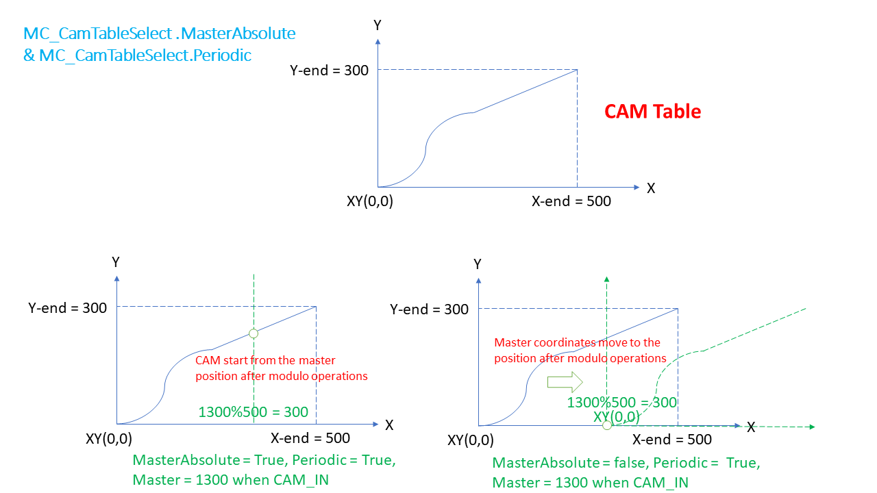
4.33.2. Definition of MasterAbsolute#
MasterAbsolute=TRUEThe cam is started at the current master position.
If Periodic=True, master position will be evaluated by modulo operations of the master value range.
MasterAbsolute=FALSESets the zero point of the master to the current master position or to the position at the end of the previous cam.
The MasterAbsolute=FALSE mode may be used only if the value 0 is in the master value range because the evaluation of the cam is started at this position.
4.33.3. Interaction of MC_CamIn.StartMode and MC_CamTableSelect.SlaveAbsolute#
MC_CamIn.StartMode |
MC_CamTableSelect.SlaveAbsolute |
MC_CamIn.StartMode: New value |
|---|---|---|
absolute |
TRUE |
absolute |
absolute |
FALSE |
relative |
relative |
TRUE |
relative |
relative |
FALSE |
relative |
4.33.4. Definition of StartMode#
StartMode = mcAbsoluteWhen starting a new cycle, the cam is evaluated independent of the current position of the slave. This can lead to jumps if the slave position to the master start position deviates from that of the master end position.
StartMode = mcRelativeThe new cam is started allowing for the current slave position. The position that the slave has after the end of the previous cycle is added as a slave offset to the new evaluations of the cam. Jumps can also occur if the slave position at the master start position is not 0.
4.33.5. Combination effect of StartMode, MC_CamTableSelect.Periodic and MC_CamTableSelect.MasterAbsolute on execution#
MC_CamTableSelect.Periodic & MC_CamTableSelect.MasterAbsolute's effect on execution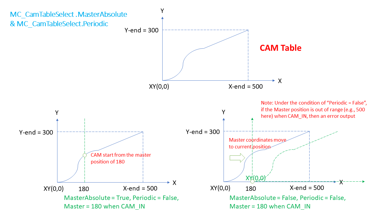
StartMode's effect on execution if MasterAbsolute = True & Periodic = False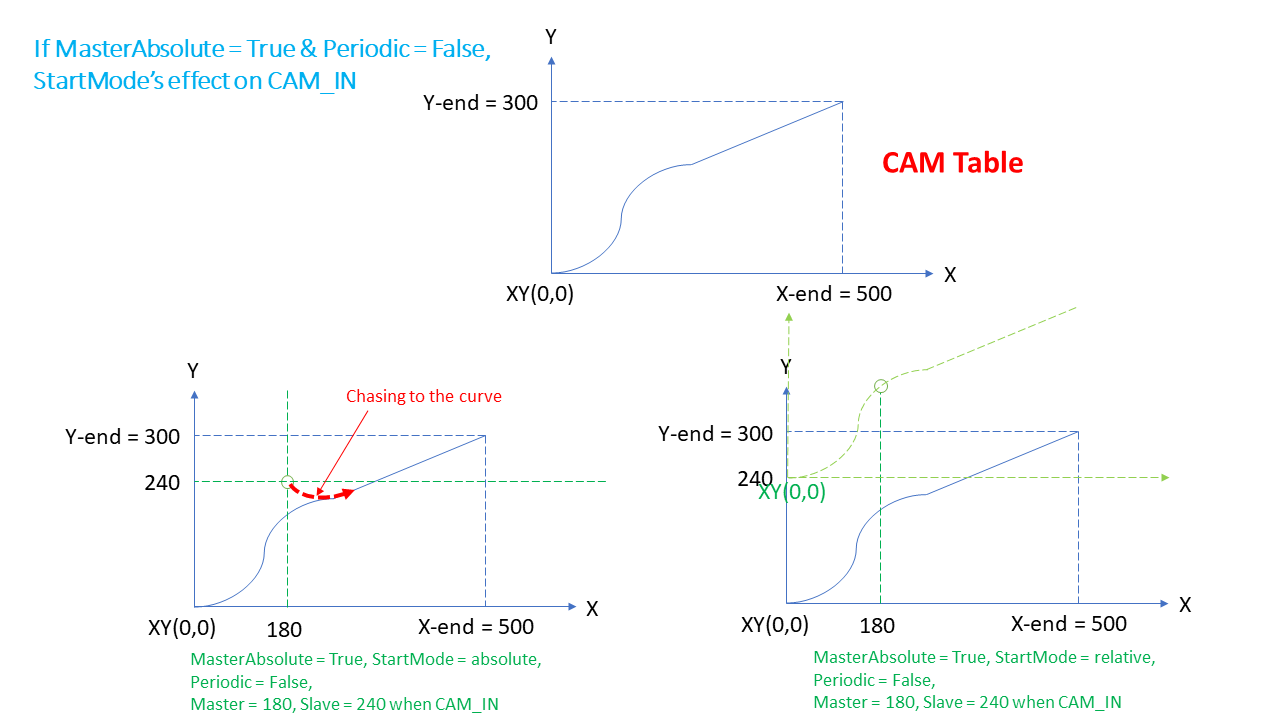
StartMode's effect on execution if MasterAbsolute = False & Periodic = False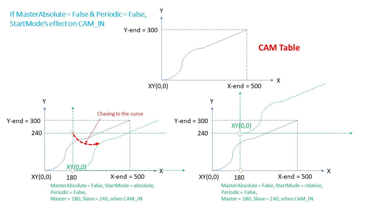
StartMode = absolute & Periodic = True on execution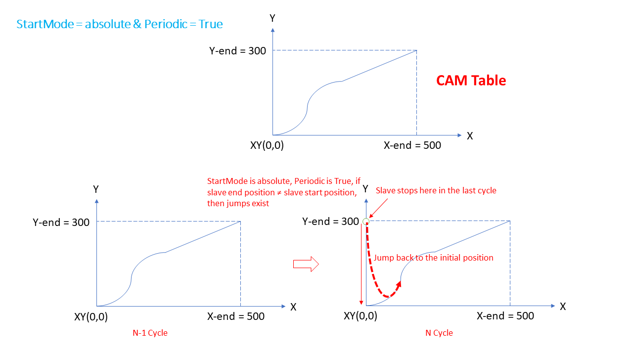
StartMode = relative & Periodic = True on execution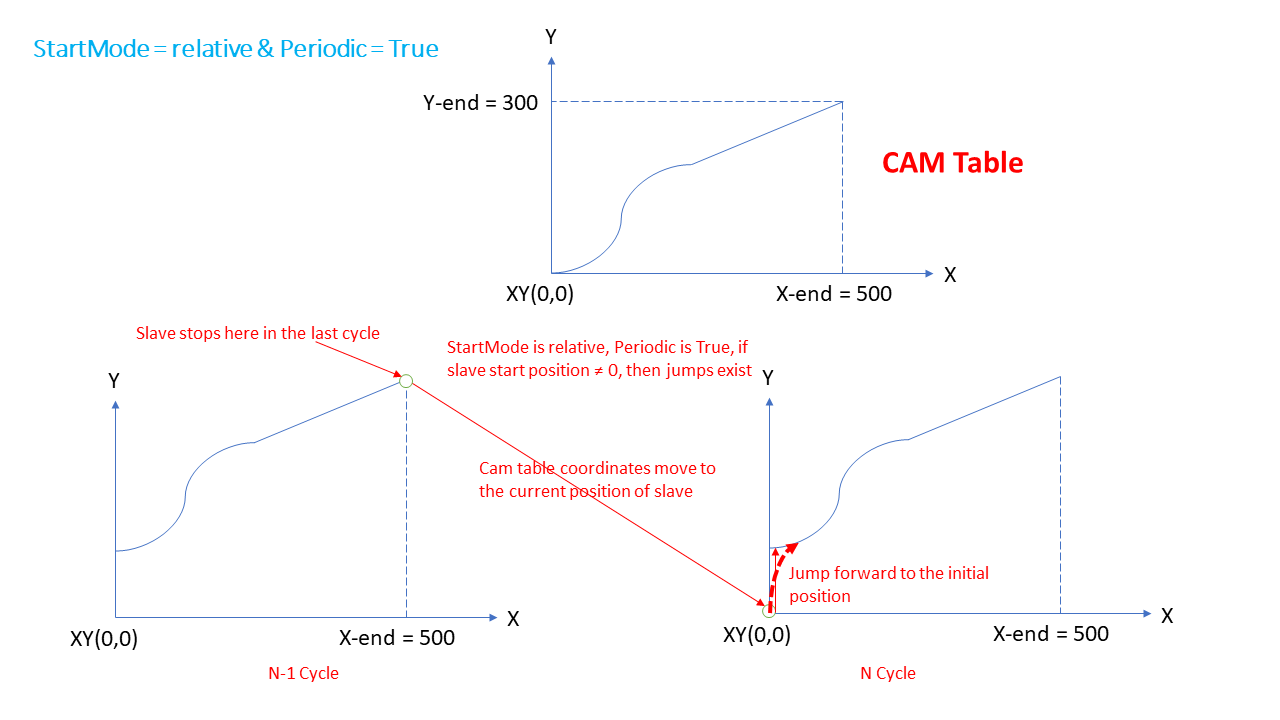
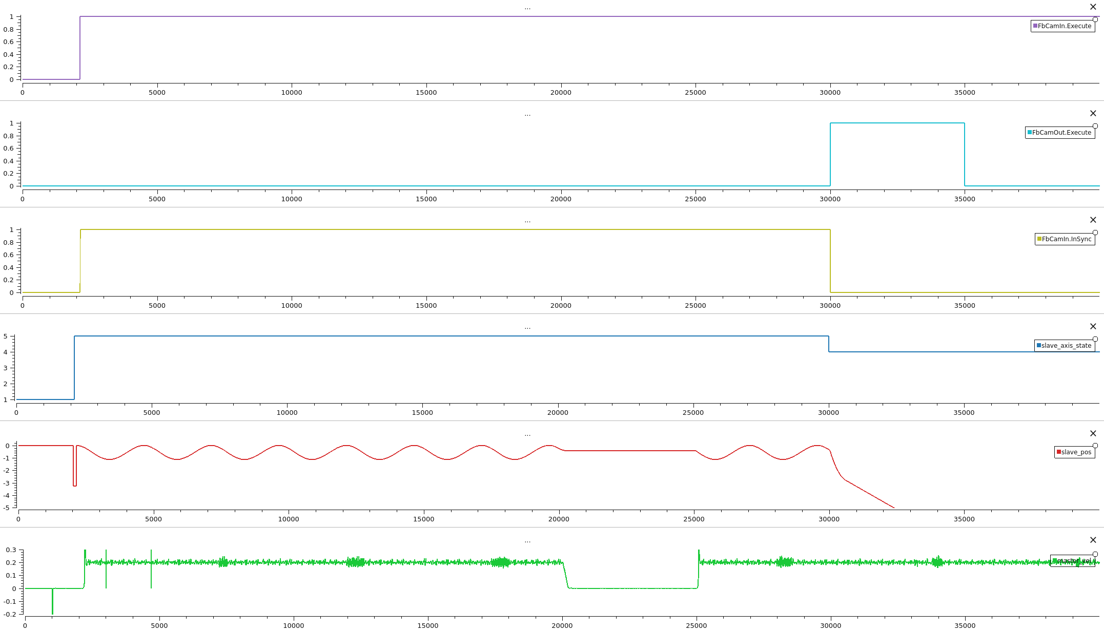
4.33.6. MC_CamIn Diagram#
4.34. MC_CamOut#
The FB disengages the Slave axis from Master axis immediately.
4.34.1. MC_CamOut inputs/outputs#
FB-Name |
MC_CamOut |
|
|---|---|---|
VAR_IN_OUT |
||
Slave |
AXIS_REF |
Reference to the Slave Axis |
VAR_INPUT |
||
Execute |
BOOL |
Start to disengage the slave from the master |
Deceleration |
LREAL |
Max deceleration of slave |
Jerk |
LREAL |
Max jerk of slave |
VAR_OUTPUT |
||
Done |
BOOL |
Start to disengage the slave from the master |
Busy |
BOOL |
The FB is not finished and new output values are to be expected |
Error |
BOOL |
Signals that an error has occurred within the Function Block |
ErrorID |
MC_ERROR_CODE |
Error identification |
4.35. MC_GearIn#
The FB commands a ratio between the VELOCITY of the slave and master axis.
4.35.1. MC_GearIn inputs/outputs#
FB-Name |
MC_GearIn |
|
|---|---|---|
VAR_IN_OUT |
||
Master |
AXIS_REF |
Reference to the master axis |
Slave |
AXIS_REF |
Reference to the slave axis |
VAR_INPUT |
||
Execute |
BOOL |
Start the gearing process at the rising edge |
RatioNumerator |
INT |
Gear ratio Numerator |
RatioDenominator |
UINT |
Gear ratio Denominator |
Acceleration |
REAL |
Acceleration for gearing in |
Deceleration |
REAL |
Deceleration for gearing in |
Jerk |
REAL |
Jerk of Gearing |
InGearThreshold |
REAL |
Acceptable velocity difference between master and slave axis |
VAR_OUTPUT |
||
InGear |
BOOL |
Is TRUE if the set value = the commanded value |
Busy |
BOOL |
The FB is not finished and new output values are to be expected |
Active |
BOOL |
Indicates that the FB has control on the axis |
Error |
BOOL |
Signals that an error has occurred within the Function Block |
ErrorID |
MC_ERROR_CODE |
Error identification |
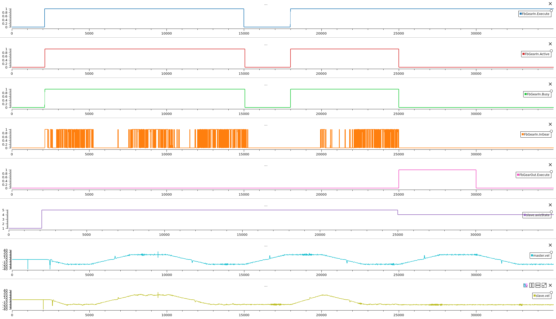
4.35.2. MC_GearIn Diagram#
4.36. MC_GearOut#
The FB disengages the Slave axis from the Master axis.
4.36.1. MC_GearOut inputs/outputs#
FB-Name |
MC_GearOut |
|
|---|---|---|
VAR_IN_OUT |
||
Slave |
AXIS_REF |
Reference to the slave axis |
VAR_INPUT |
||
Execute |
BOOL |
Start the gearing process at the rising edge |
VAR_OUTPUT |
||
Done |
BOOL |
Disengaging completed |
Busy |
BOOL |
The FB is not finished and new output values are to be expected |
Error |
BOOL |
Signals that an error has occurred within the Function Block |
ErrorID |
MC_ERROR_CODE |
Error identification |
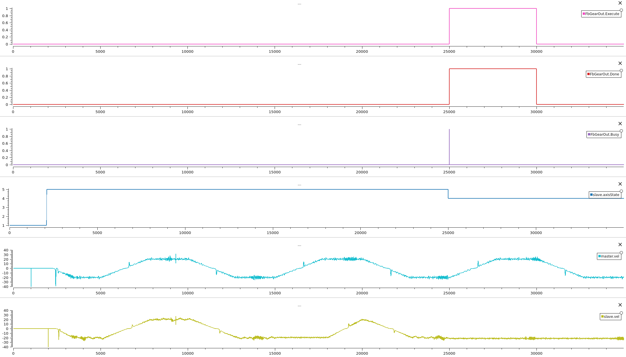
4.36.2. MC_GearOut Diagram#
4.37. MC_GearInPos#
This Function Block commands a gear ratio between the position of the slave and master axes from the synchronization point onward.
4.37.1. MC_GearInPos inputs/outputs#
FB-Name |
MC_GearIn |
|
|---|---|---|
VAR_IN_OUT |
||
Master |
AXIS_REF |
Reference to the master axis |
Slave |
AXIS_REF |
Reference to the slave axis |
VAR_INPUT |
||
Execute |
BOOL |
Start the gearing process at the rising edge |
RatioNumerator |
INT |
Gear ratio Numerator |
RatioDenominator |
UINT |
Gear ratio Denominator |
MasterSyncPosition |
LREAL |
The position of the master in the CAM profile where the slave is in-sync with the master |
SlaveSyncPosition |
LREAL |
Slave Position at which the axes are running in sync |
MasterStartDistance |
LREAL |
Master Distance for gear in procedure |
Velocity |
LREAL |
Maximum Velocity during the time difference ‘StartSync’ and ‘InSync’ |
Acceleration |
LREAL |
Maximum Acceleration during the time difference ‘StartSync’ and ‘InSync’ |
Deceleration |
LREAL |
Maximum Deceleration during the time difference ‘StartSync’ and ‘InSync’ |
Jerk |
LREAL |
Maximum Jerk during the time difference ‘StartSync’ and ‘InSync’ |
PosSyncFactor |
LREAL |
Acceptable position difference between master’s actual position and master’s sync position |
VelSyncFactor |
LREAL |
Acceptable velocity difference between slave’s actual velocity and slave velocity in gear |
VAR_OUTPUT |
||
StartSync |
BOOL |
Commanded gearing start |
InSync |
BOOL |
Is TRUE if the set value = the commanded value |
Busy |
BOOL |
The FB is not finished and new output values are to be expected |
Active |
BOOL |
Indicates that the FB has control on the axis |
CommandAborted |
BOOL |
‘Command’ is aborted by another command |
Error |
BOOL |
Signals that an error has occurred within the Function Block |
ErrorID |
MC_ERROR_CODE |
Error identification |
4.37.2. MC_GearInPos Timing Diagram#
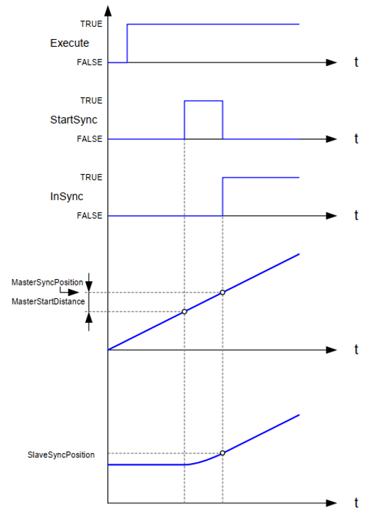
With BufferMode Aborting, any previous motion is continued until the master crosses the position MasterSyncPosition - MasterStartDistance in the correct direction. At that point in time the output StartSync is set. When a stop command is executed on the slave axis before the synchronization has happened, it will inhibit the synchronization and the function block issues CommandAborted = TRUE.
If the MasterStartDistance is not specified (indicated by a non-positive value), the function block calculates the setting start distance point so that synchronization starts at the current master position.
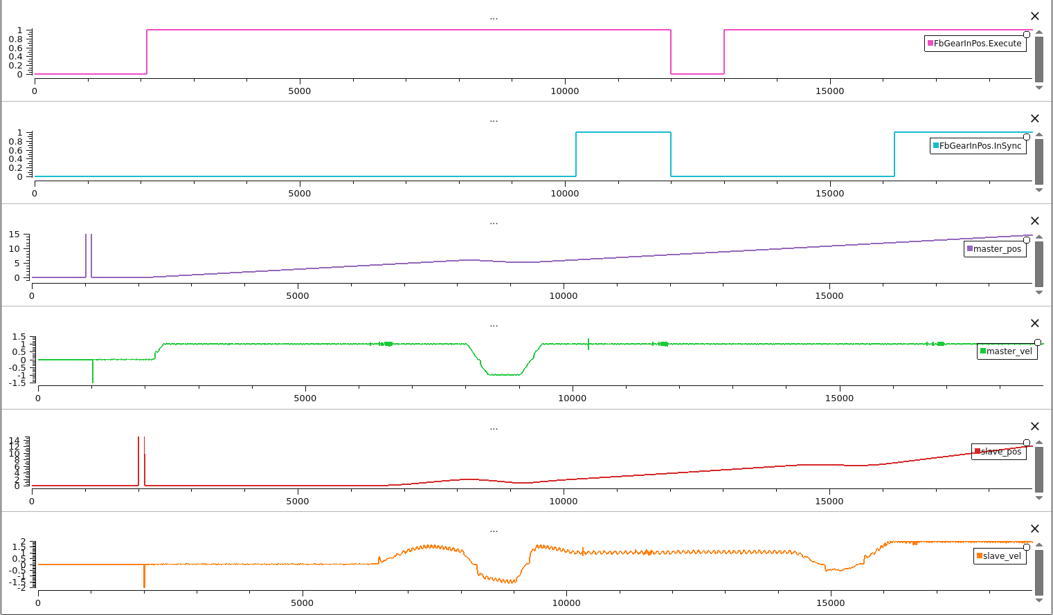
4.37.3. MC_GearInPos Executing Diagram#
4.38. MC_DigitalCamSwitch#
This Function Block is the analogy to switches on a motor shaft: it commands a group of discrete output bits to switch in analogy to a set of mechanical cam controlled switches connected to an axis. Forward and backward movements are allowed.
4.38.1. MC_DigitalCamSwitch#
FB-Name |
MC_DigitalCamSwitch |
|
|---|---|---|
VAR_IN_OUT |
||
Axis |
AXIS_REF |
Reference to the axis |
Switches |
MC_CAMSWITCH_REF |
Reference to the switching actions. |
Outputs |
MC_OUTPUT_REF |
Reference to the signal outputs, directly related to the referenced tracks. (max. 32 per function block) |
TrackOptions |
MC_TRACK_REF |
Reference to structure containing track related properties, e.g. the ON and OFF compensations per output/track |
VAR_INPUT |
||
Enable |
BOOL |
Enables the ‘Switches’ outputs |
EnableMask |
DWORD |
32 bits of BOOL. Enables the different tracks. Least significant data is related to the lowest TrackNumber. |
ValueSource |
MC_SOURCE |
Defines the source for axis values (e.g. positions) |
VAR_OUTPUT |
||
InOperation |
BOOL |
The commanded tracks are enabled |
Busy |
BOOL |
The FB is not finished and new output values are to be expected |
Error |
BOOL |
Signals that an error has occurred within the Function Block |
ErrorID |
MC_ERROR_CODE |
Error identification |
4.38.2. McCamSwitch struct and MC_CAMSWITCH_REF struct#
Struct-Name |
McCamSwitch |
|
|---|---|---|
TrackNumber |
UINT |
TrackNumber is the reference to the track |
FirstOnPosition |
LREAL |
Lower boundary where the switch is ON |
LastOnPosition |
LREAL |
Upper boundary where the switch is ON |
AxisDirection |
INT |
Both (=0; Default); Positive (1); Negative (2) |
CamSwitchMode |
INT |
Position based (=0; Default); Time based (=1) |
Duration |
LREAL |
Coupled to time based CamSwitchMode (In seconds) |
Struct-Name |
MC_CAMSWITCH_REF |
|
|---|---|---|
SwitchNumber |
USINT |
Number of switches in cam switch array |
CamSwitchPointer |
McCamSwitch * |
Pointer to the first element of cam switch array |
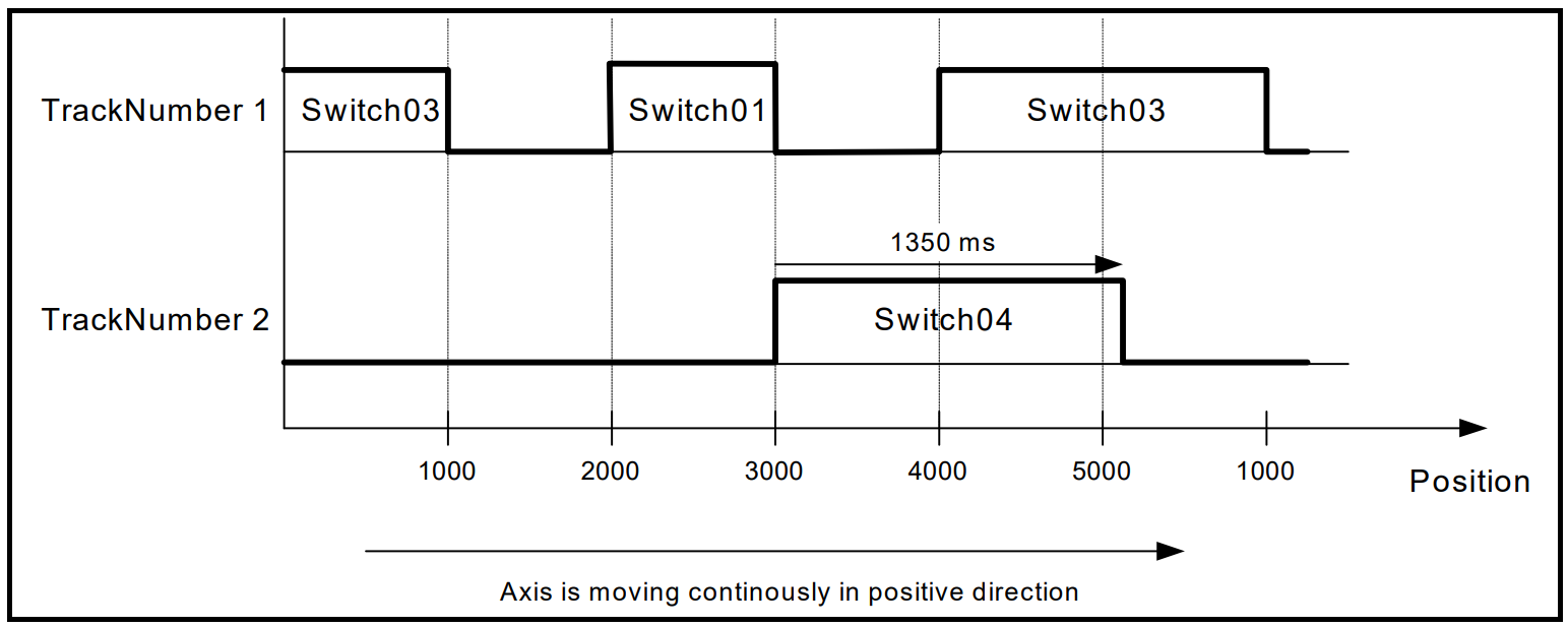
Here is an example of MC_CAMSWITCH_REF:
Parameter |
Switch01 |
Switch02 |
Switch03 |
Switch04 |
… |
SwitchN |
|---|---|---|---|---|---|---|
TrackNumber |
1 |
1 |
1 |
2 |
||
FirstOnPosition |
2000 |
2500 |
4000 |
3000 |
||
LastOnPosition |
3000 |
3000 |
1000 |
– |
||
AxisDirection |
1=Pos |
2=Neg |
0=Both |
0=Both |
||
CamSwitchMode |
0=Position |
0=Position |
0=Position |
1=Time |
||
Duration |
– |
– |
– |
1.35 |
4.38.3. McTrack struct#
Struct-Name |
McCamSwitch |
|
|---|---|---|
ModuloPosition |
BOOL |
Cam positions are interpreted as modulo positions when TRUE |
ModuloFactor |
LREAL |
The length of a modulo cycle in the positioning unit of the axis |
OnCompensation |
LREAL |
Compensation time with which the switching on is advanced or delayed in time per track (In seconds) |
OffCompensation |
LREAL |
Time compensation the switching off is delayed per track (In seconds) |
Hysteresis |
LREAL |
Distance from the switching point (in positive and negative direction) in which the switch is not executed until the axis has left this area, in order to avoid multiple switching around the switching point (Not available yet) |
MC_TRACK_REF is defined as reference pointer to McTrack.
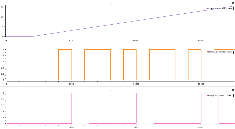
The example below uses the values from the example for MC_CAMSWITCH_REF above. It uses neither On/OffCompensation, nor hysteresis. This is the behavior of the outputs, when the axis is moving continuously in the positive direction. The track use a modulo factor of 5000 unit long.
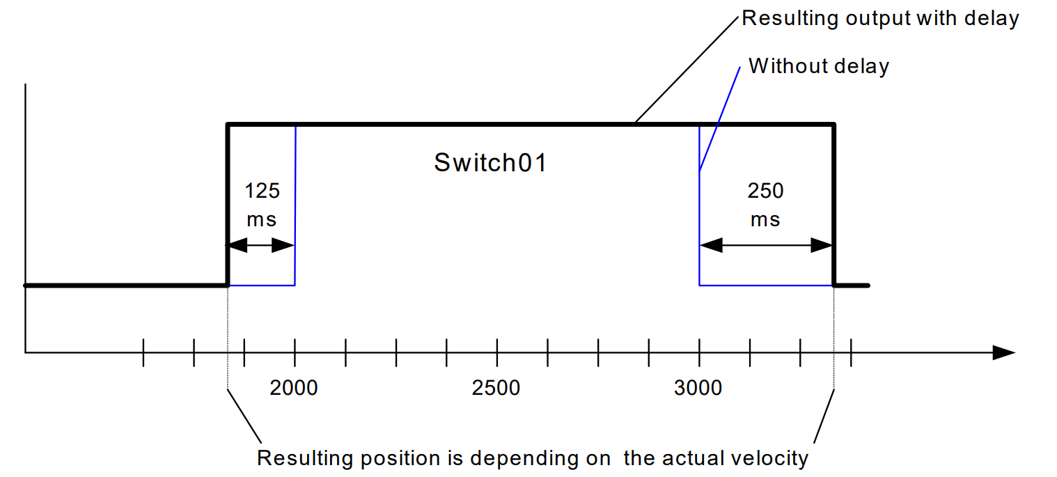
This example is detailed description of Switch01 and additionally uses OnCompensation -125ms and OffCompensation +250ms
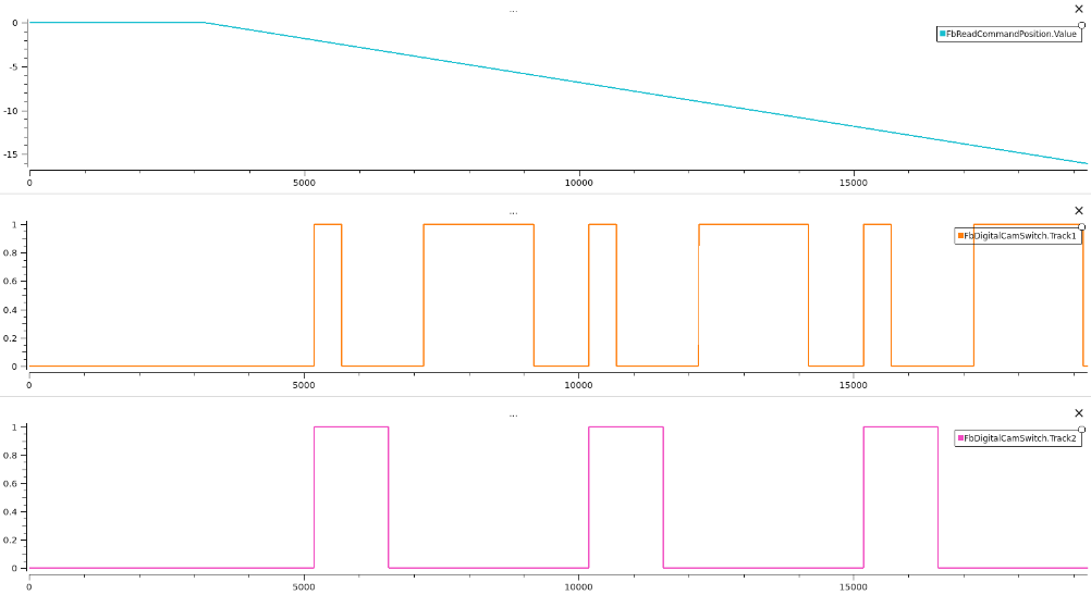
Below the behavior of the outputs, when the axis is moving continuously in the negative direction without On/OffCompensation and without Hysteresis.
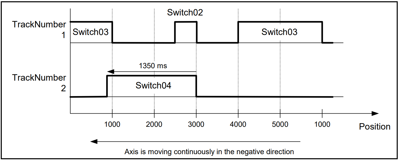
4.38.4. MC_DigitalCamSwitch Executing Diagram#
1. RTmotion trajectory planning#
Servo motors running in Cyclic Synchronous Position Mode (CSP), Cyclic Synchronous Velocity Mode (CSV) or Cyclic Synchronous Torque Mode (CST) mode need to receive commands in real-time cycle time, such as 1ms cycle time. This requires trajectory planning algorithms to interpolate in delta time interval same to the cycle time.
5.1. S-curve trajectory planning#
S-curve trajectory planning is one algorithm used by the PLCopen function blocks for single axis trajectory interpolation. When driving a motor to an absolute or additive position, the motors always try to accelerate its velocity to its maximum value and decelerate before it reaches the target position. If the acceleration during this process is not continuous or linear piece-wise, some infinite jerk spikes may happen, which can cause efforts and stresses on the mechanical system of motors that results in detrimental or undesired vibrational effects. Therefore, the S-curve trajectory planning is necessary.
A sample implementation of the S-curve algorithm is provided in ECI for reference design. For more information of S-curve planning, refer to “Trajectory Planning for Automatic Machines and Robots-Springer (2008)” by Luigi Biagiotti, Claudio Melchiorri.
Some s-curve planner tests in <RTmotion_ROOT_DIR>/test/online_scurve_test.cpp:
Test1
Input:
S0: 0, S1: 50, V0: 0, V1: 0, A0: 0, A1: 0Constraints:
Vmin: -10, Vmax: 10, Amin: -10, Amax: 10, Jmin: -30, Jmax: 30

Figure 17. Scurve test 1 result
Test2
Input:
S0: 0, S1: 5, V0: 0, V1: 0, A0: 0, A1: 0Constraints:
Vmin: -10, Vmax: 10, Amin: -10, Amax: 10, Jmin: -30, Jmax: 30
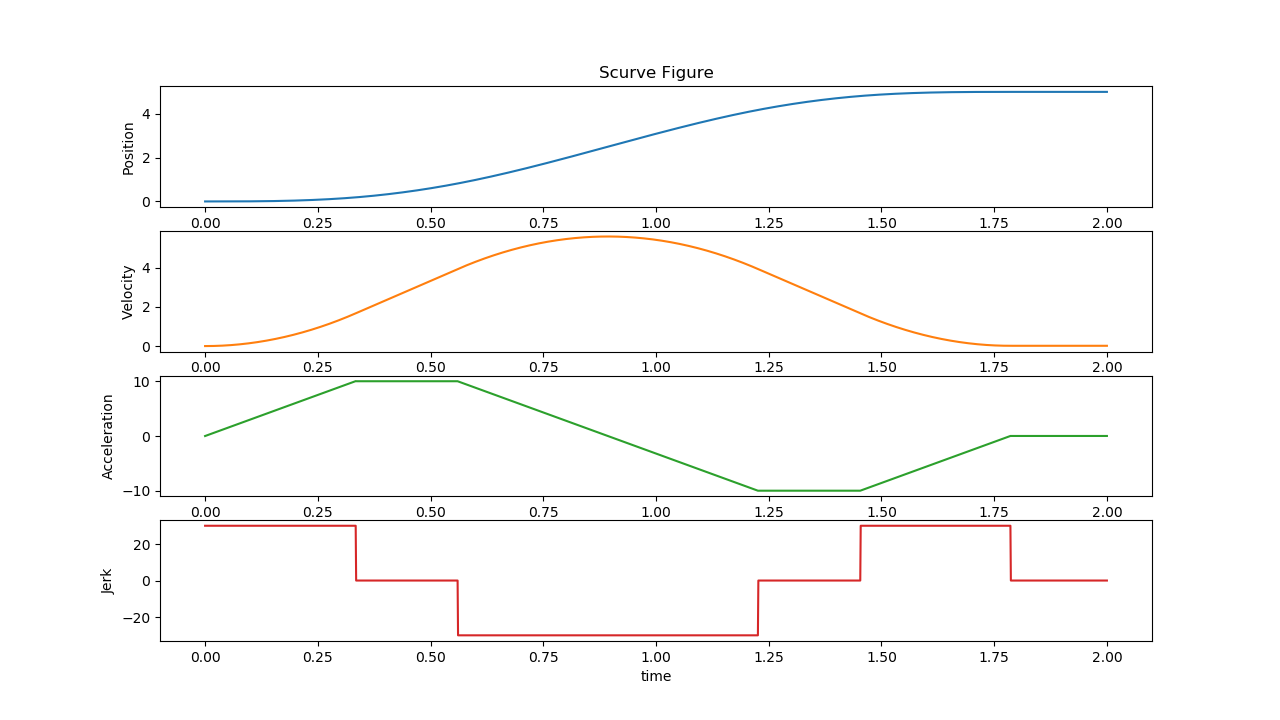
Figure 18. Scurve test 2 result
Test3
Input:
S0: 0, S1: 5, V0: 5, V1: 3, A0: 3, A1: 5Constraints:
Vmin: -10, Vmax: 10, Amin: -10, Amax: 10, Jmin: -30, Jmax: 30
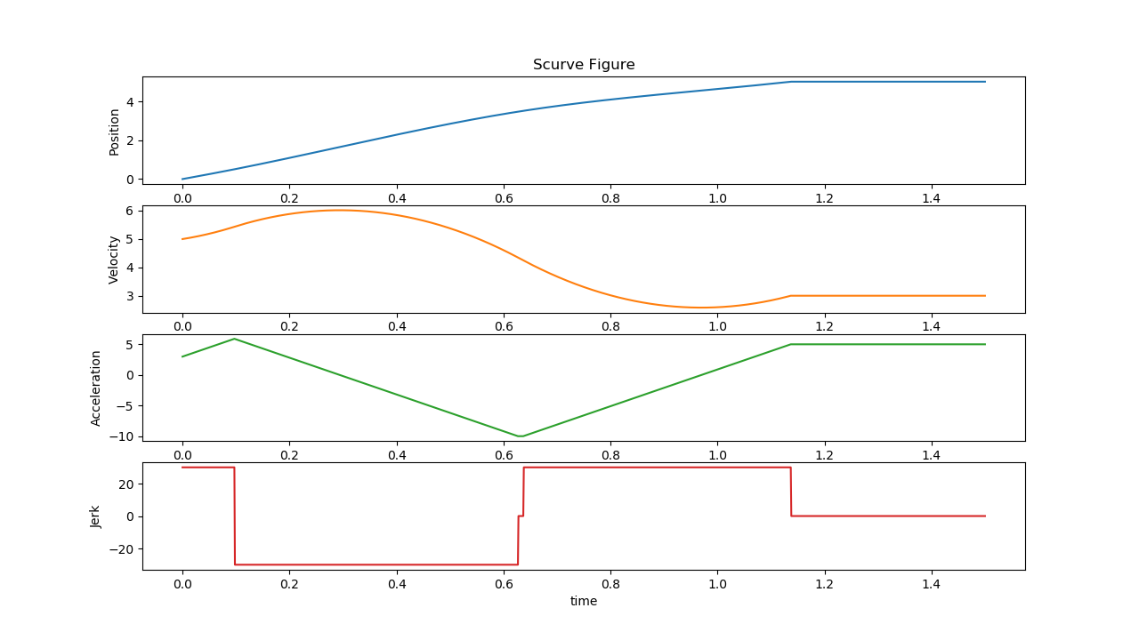
Figure 19. Scurve test 3 result
Test4
Input:
S0: 0, S1: 5, V0: 5, V1: 3, A0: -4, A1: 2Constraints:
Vmin: -10, Vmax: 10, Amin: -10, Amax: 10, Jmin: -30, Jmax: 30
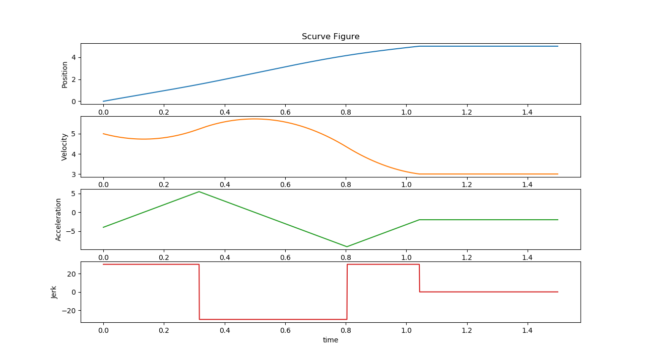
Figure 20. Scurve test 4 result
Test5
Input:
S0: 0, S1: 50, V0: 15, V1: 3, A0: -4, A1: 2Constraints:
Vmin: -10, Vmax: 10, Amin: -10, Amax: 10, Jmin: -30, Jmax: 30
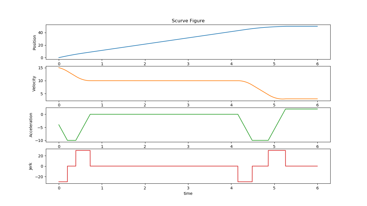
Figure 21. Scurve test 5 result
Test6
Input:
S0: 0, S1: 50, V0: 15, V1: 20, A0: -4, A1: 2Constraints:
Vmin: -10, Vmax: 10, Amin: -10, Amax: 10, Jmin: -30, Jmax: 30
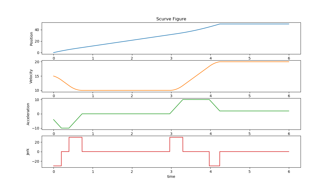
Figure 22. Scurve test 6 result
Test7
Input:
S0: 0, S1: 20, V0: 15, V1: 20, A0: -4, A1: 2Constraints:
Vmin: -10, Vmax: 10, Amin: -10, Amax: 10, Jmin: -30, Jmax: 30
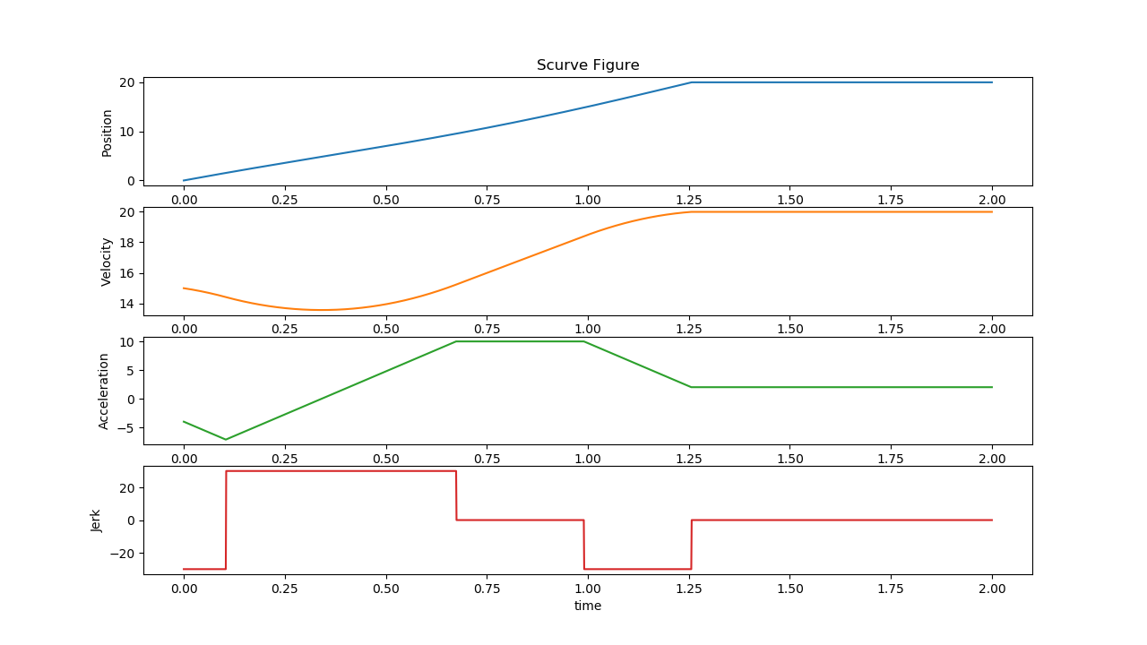
Figure 23. Scurve test 7 result
Test8
Input:
S0: 0, S1: 3.14, V0: 0, V1: 0, A0: 0, A1: 0Constraints:
Vmin: -1.57, Vmax: 1.57, Amin: -3.14, Amax: 3.14, Jmin: -500, Jmax: 500
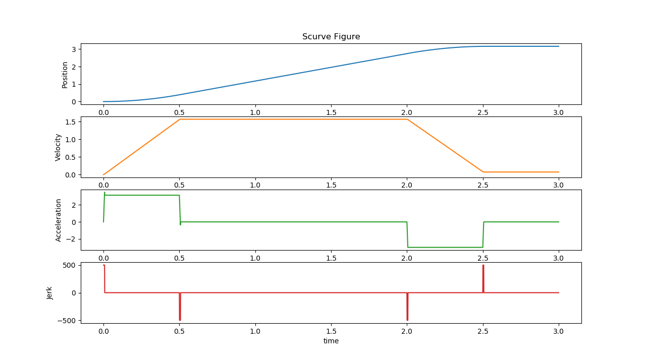
Figure 24. Scurve test 8 result
Test9
Input:
S0: 0, S1: 10, V0: 1, V1: 0, A0: 0, A1: 0Constraints:
Vmin: -10, Vmax: 10, Amin: -10, Amax: 10, Jmin: -30, Jmax: 30
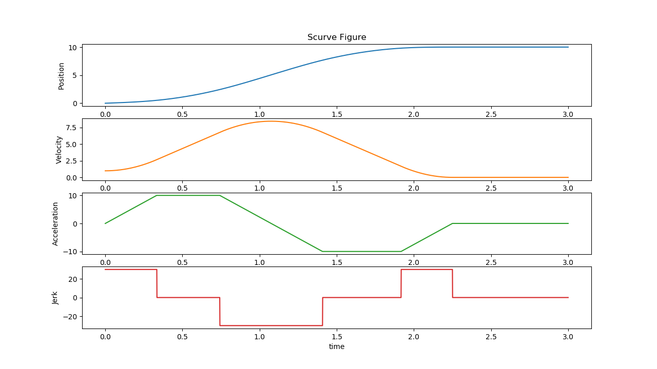
Figure 25. Scurve test 9 result
Some s-curve planner tests in <RTmotion_ROOT_DIR>/test/planner_test.cpp:
VelocityUp
Input:
S0 5, V0: -1, V1: 10Constraints:
Vmax: 5, Amax 10, Jmax: 30
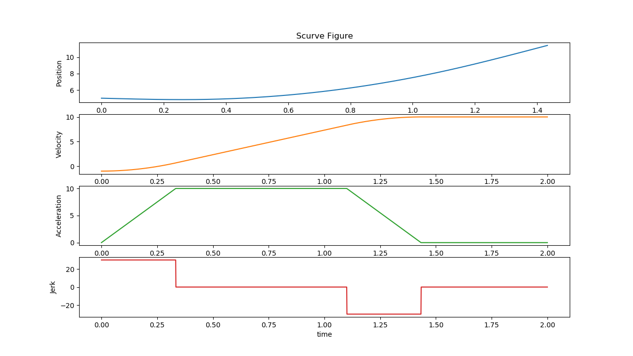
Figure 26. Planner test VelocityUp result
VelocityDown
Input:
S0 5, V0: 10, V1: -5Constraints:
Vmax: 5, Amax 10, Jmax: 30
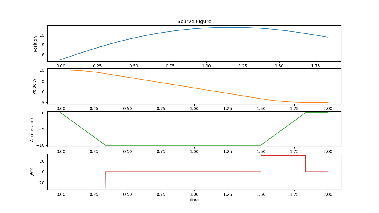
Figure 27. Planner test VelocityDown result
Example_3_9
Input:
S0 0, S1: 10, V0: 1, V1: 0Constraints:
Vmax: 5, Amax 10, Jmax: 30
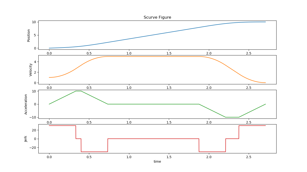
Figure 28. Planner test Example_3_9 result
Example_3_10
Input:
S0 0, S1: 10, V0: 1, V1: 0Constraints:
Vmax: 10, Amax 10, Jmax: 30
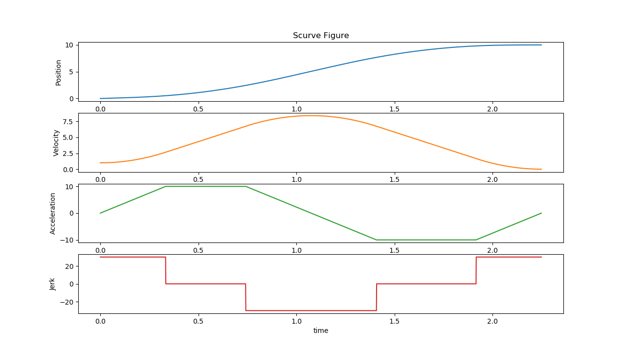
Figure 29. Planner test Example_3_10 result
Example_3_11
Input:
S0 0, S1: 10, V0: 7, V1: 0Constraints:
Vmax: 10, Amax 10, Jmax: 30
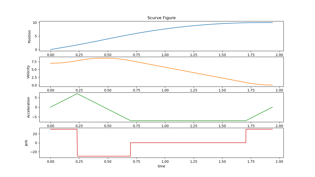
Figure 30. Planner test Example_3_11 result
Example_3_12
Input:
S0 0, S1: 10, V0: 7.5, V1: 0Constraints:
Vmax: 10, Amax 10, Jmax: 30
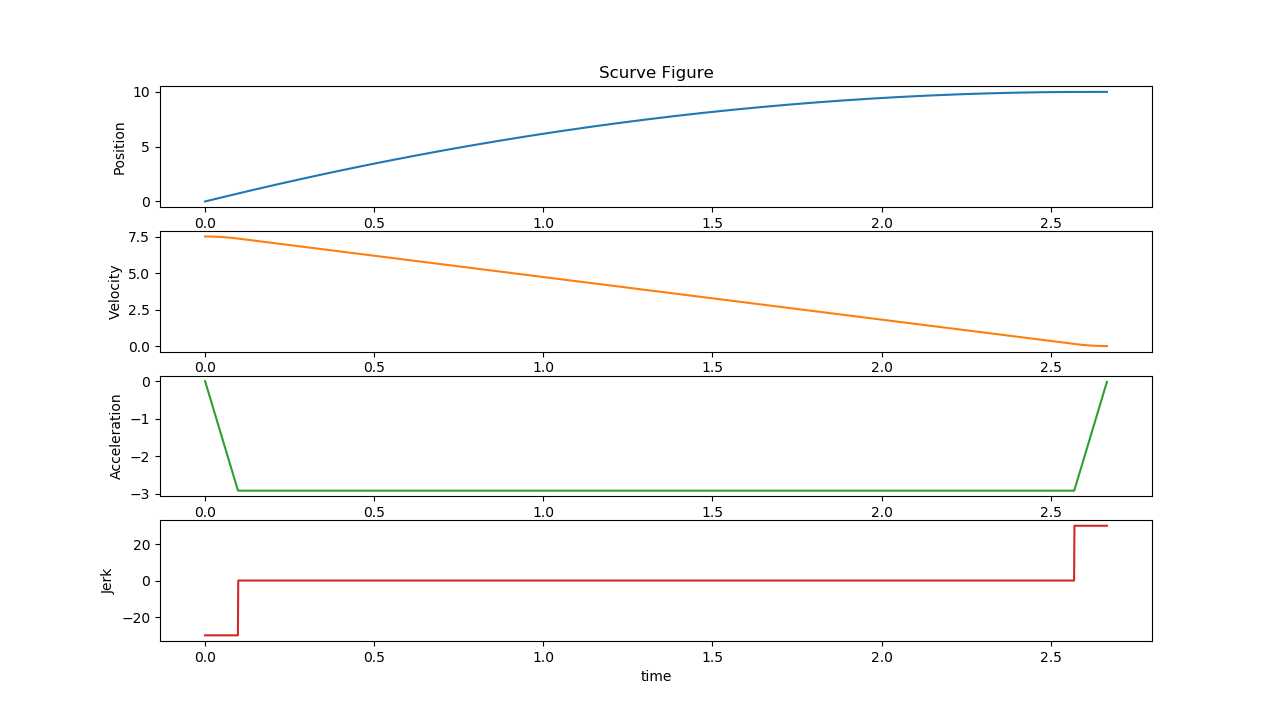
Figure 31. Planner test Example_3_12 result
Example_3_13
Input:
S0 0, S1: 10, V0: 0, V1: 0Constraints:
Vmax: 10, Amax 20, Jmax: 30
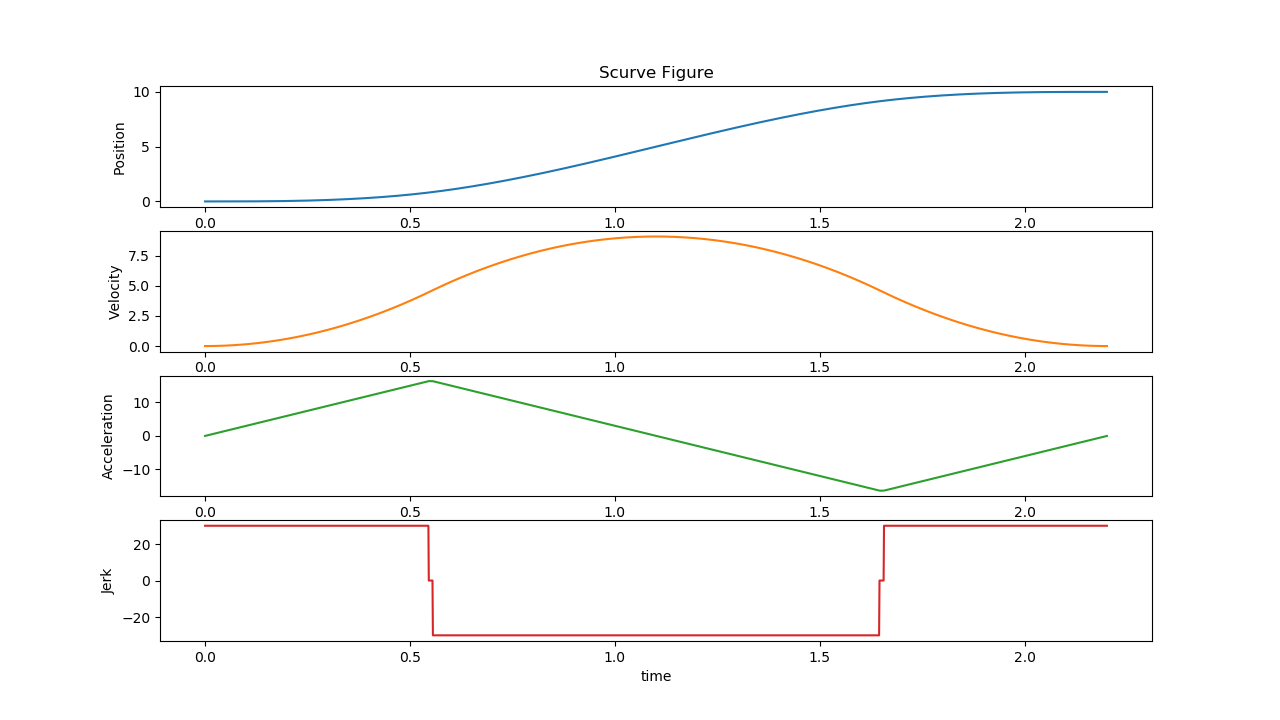
Figure 32. Planner test Example_3_13 result
Test_Negative
Input:
S0 10, S1: 0, V0: 1, V1: 0Constraints:
Vmax: 5, Amax 10, Jmax: 30
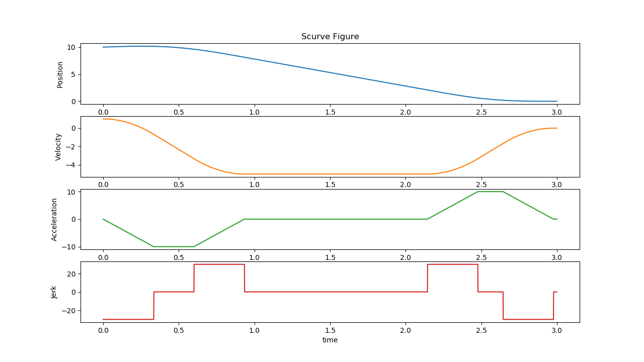
Figure 33. Planner test Test_Negative result
6. RTmotion C++ example#
This section provides examples of how to call RTmotion functions in C++ applications.
6.1. Build RTmotion#
At the first step, build and install Ruckig:
git clone -b v0.9.2 https://github.com/pantor/ruckig.git
cd ruckig
mkdir build && cd build
cmake -DCMAKE_BUILD_TYPE=Release ..
make
sudo make install
Build RTmotion and its minimum example:
cd <RTmotion directory>
mkdir build & cd build
# For the next step, pick one of the two options:
# - Option 1: If build on PREEMPT Linux, run the next command
cmake ..
# - Option 2: If build on Xenomai, run the next command
cmake .. -DCOBALT=ON -DXENOMAI_DIR=/usr/xenomai
make
6.2. Run RTmotion minimum example#
The RTmotion minimum example shows how to run RTmotion function blocks (MC_Power, MC_MoveRelative, MC_ReadActualPosition, MC_ReadActualVelocity) on a virtual axis. The program uses MC_Power to power on the axis. Then it uses MC_MoveRelative to move the axis to a distance with 200 units relative to the current position (by default 0 at start time). When the MC_MoveRelative is done, a negative 200 units distance is set and the MC_MoveRelative is re-triggered to move the axis back to its original position.
# A runable should has already been build in this folder
cd <RTmotion directory>/build/src

# Argument parameters:
#   -c : Index of CPU core isolated for real-time tasks
#   -t : The expected time to run this example (s)
taskset -c <CPUID> multi-axis -t <running time in seconds>
This is the source code for a minimal example, code explanation has been added via comments.
An example with one virtual axis:
/*
* Copyright (c) 2020 Intel Corporation
* Licensed under the Apache License, Version 2.0 (the "License");
* you may not use this file except in compliance with the License.
* You may obtain a copy of the License at
*
* http://www.apache.org/licenses/LICENSE-2.0
*
* Unless required by applicable law or agreed to in writing, software
* distributed under the License is distributed on an "AS IS" BASIS,
* WITHOUT WARRANTIES OR CONDITIONS OF ANY KIND, either express or implied.
* See the License for the specific language governing permissions and
* limitations under the License.
*/
/**
* @file multi-axis.cpp
*
* Maintainer: Yu Yan <yu.yan@intel.com>
*
*/
#include <signal.h>
#include <pthread.h>
#include <sys/mman.h>
#include <getopt.h>
#include <fb/common/include/axis.hpp>
#include <fb/common/include/global.hpp>
#include <fb/public/include/fb_power.hpp>
#include <fb/public/include/fb_move_relative.hpp>
#include <fb/public/include/fb_move_velocity.hpp>
#include <fb/public/include/fb_read_actual_position.hpp>
#include <fb/public/include/fb_read_actual_velocity.hpp>
static unsigned int cycle_us =
1000; // Define real-time cycle time as 1 ms (micro-seconds)
#define NSEC_PER_MICROSEC \
1000 // Record execution time for 1000 times for 1 s (seconds)
#define AXIS_NUM 1 // Set axis number as 1
static volatile int run = 1;
static pthread_t cyclic_thread;
using namespace RTmotion;
void* my_thread(void* /*arg*/)
{
AXIS_REF axis[AXIS_NUM]; // "AXIS_REF" is the pointer to axis objects
for (auto& ax : axis)
{
ax = new Axis(); // "AXIS_REF" should be initialized by "new" operator
ax->setAxisId(1);
}
/* AxisConfig contains multiple configurations for the axis (= defaul value):
- MC_SERVO_CONTROL_MODE mode_ = mcServoControlModePosition;
- uint64_t encoder_count_per_unit_ = 1000000;
- uint64_t node_buffer_size_ = 2;
- bool sw_vel_limit_ = false;
- double vel_limit_ = 5000.0;
- bool sw_acc_limit_ = false;
- double acc_limit_ = 5000.0;
- bool sw_range_limit_ = false;
- double pos_positive_limit_ = 5000.0;
- double pos_negative_limit_ = 5000.0;
- double frequency_ = 1000.0;
*/
AxisConfig config[AXIS_NUM];
for (size_t i = 0; i < AXIS_NUM; i++)
{
config[i].frequency_ = 1.0 / cycle_us * 1000000;
axis[i]->setAxisConfig(&config[i]);
}
Servo* servo[AXIS_NUM];
for (size_t i = 0; i < AXIS_NUM; i++)
{
servo[i] = new Servo(); // Create virtual servo motors
axis[i]->setServo(servo[i]);
}
printf("Axis initialized.\n");
FbPower fb_power[AXIS_NUM]; // Initialize MC_Power
for (size_t i = 0; i < AXIS_NUM; i++)
{
fb_power[i].setAxis(axis[i]);
fb_power[i].setEnable(mcTRUE);
fb_power[i].setEnablePositive(mcTRUE);
fb_power[i].setEnableNegative(mcTRUE);
}
FbMoveRelative fb_move_rel[AXIS_NUM]; // Initialize MC_MoveRelative
for (size_t i = 0; i < AXIS_NUM; i++)
{
fb_move_rel[i].setAxis(axis[i]);
fb_move_rel[i].setContinuousUpdate(mcFALSE);
fb_move_rel[i].setDistance(200);
fb_move_rel[i].setVelocity(500);
fb_move_rel[i].setAcceleration(500);
fb_move_rel[i].setDeceleration(500);
fb_move_rel[i].setJerk(5000);
fb_move_rel[i].setBufferMode(mcAborting);
}
FbReadActualPosition read_pos[AXIS_NUM]; // Initialize MC_ReadActualPosition
for (size_t i = 0; i < AXIS_NUM; i++)
{
read_pos[i].setAxis(axis[i]);
read_pos[i].setEnable(mcTRUE);
}
FbReadActualVelocity read_vel[AXIS_NUM]; // Initialize MC_ReadActualVelocity
for (size_t i = 0; i < AXIS_NUM; i++)
{
read_vel[i].setAxis(axis[i]);
read_vel[i].setEnable(mcTRUE);
}
printf("Function block initialized.\n");
struct timespec next_period;
struct sched_param param = {};
param.sched_priority = 99; // Set real-time thread priority
/* Set real-time thread schedule policy as preemptable "SCHED_FIFO" */
pthread_setschedparam(pthread_self(), SCHED_FIFO, ¶m);
clock_gettime(CLOCK_MONOTONIC, &next_period);
while (run != 0)
{
next_period.tv_nsec += cycle_us * 1000;
while (next_period.tv_nsec >= NSEC_PER_SEC)
{
next_period.tv_nsec -= NSEC_PER_SEC;
next_period.tv_sec++;
}
/* Sleep to the next cycle start time "next_period"
Using clock "CLOCK_MONOTONIC" for accurate clock time */
clock_nanosleep(CLOCK_MONOTONIC, TIMER_ABSTIME, &next_period, nullptr);
/* All the "runCycle()" functions of axes and function blocks
should be run in every real-time cycle */
for (size_t i = 0; i < AXIS_NUM; i++)
{
axis[i]->runCycle();
fb_power[i].runCycle();
fb_move_rel[i].runCycle();
read_pos[i].runCycle();
read_vel[i].runCycle();
}
/* Trigger axis movement when all axis are powered on */
mcBOOL power_on = mcTRUE;
for (auto& fb : fb_power)
power_on = (power_on == mcTRUE) && (fb.getPowerStatus() == mcTRUE) ?
mcTRUE :
mcFALSE;
/* Only enable MC_MoveRelative when the axis is powered on */
if (power_on == mcTRUE)
{
for (auto& fb : fb_move_rel)
fb.setExecute(mcTRUE);
}
/* When the MC_MoveRelative is done, reverse direction
and move back with the same relative distance */
for (auto& fb : fb_move_rel)
{
if (fb.isDone() == mcTRUE)
{
fb.setExecute(mcFALSE);
fb.setPosition(-fb.getPosition());
}
}
/* All read function blocks using "getFloatValue()" function to get the
desired value. This print is only for a demo, please do not make prints in
a real-time thread for real-life usage. Otherwise,
it will hurt real-time performance. */
printf("Joint %d, pos: %f, vel: %f\n", 0, read_pos[0].getFloatValue(),
read_vel[0].getFloatValue());
}
/* Release the memory for the axis and servo objects after the real-time task
* finishes */
for (size_t i = 0; i < AXIS_NUM; i++)
{
if (!servo[i])
{
delete servo[i];
servo[i] = nullptr;
}
if (!axis[i])
{
delete axis[i];
axis[i] = nullptr;
}
}
return nullptr;
}
/* Parse command arguments */
static void getOptions(int argc, char** argv)
{
int index;
static struct option long_options[] = {
// name has_arg flag val
{ "interval", required_argument, nullptr, 'i' },
{ "help", no_argument, nullptr, 'h' },
{}
};
do
{
index = getopt_long(argc, argv, "i:h", long_options, nullptr);
switch (index)
{
case 'i':
cycle_us = (unsigned int)atof(optarg);
printf("Time: Set running interval to %d us\n", cycle_us);
break;
case 'h':
printf("Global options:\n");
printf(" --interval -i Set cycle time (us).\n");
printf(" --help -h Show this help.\n");
exit(0);
break;
}
} while (index != -1);
}
/****************************************************************************
* Main function
***************************************************************************/
int main(int argc, char* argv[])
{
getOptions(argc, argv);
auto signal_handler = [](int /*unused*/) { run = 0; };
signal(SIGTERM, signal_handler);
signal(SIGINT, signal_handler);
mlockall(MCL_CURRENT | MCL_FUTURE);
/* Create cyclic RT-thread */
pthread_attr_t thattr;
pthread_attr_init(&thattr);
pthread_attr_setdetachstate(&thattr, PTHREAD_CREATE_JOINABLE);
if (pthread_create(&cyclic_thread, &thattr, &my_thread, nullptr))
{
fprintf(stderr, "pthread_create cyclic task failed\n");
return 1;
}
pthread_join(cyclic_thread, nullptr);
printf("End of Program\n");
return 0;
}
/****************************************************************************/
6.3. Run RTmotion with EtherCAT servo#
Running RTmotion with EtherCAT servos needs to replace the virtual servo RTmotion::Servo with a EtherCAT servo RTmotion::EcrtServo, which can be derived from RTmotion::Servo as shown here:
#include <fb/common/include/Servo.hpp>

namespace RTmotion
{
class Servo
{
public:
  Servo();
  virtual ~Servo();
  virtual MC_SERVO_ERROR_CODE setPower(mcBOOL powerStatus, mcBOOL& isDone);
  virtual MC_SERVO_ERROR_CODE setPos(mcDINT pos);
  virtual MC_SERVO_ERROR_CODE setVel(mcDINT vel);
  virtual MC_SERVO_ERROR_CODE setTorque(mcLREAL torque);
  virtual MC_SERVO_ERROR_CODE setMaxProfileVel(mcDWORD vel);
  virtual MC_SERVO_ERROR_CODE setMode(mcSINT mode);
  virtual MC_SERVO_ERROR_CODE setHomeEnable(mcBOOL enable);
  virtual mcDINT pos();
  virtual mcDINT vel();
  virtual mcDINT acc();
  virtual mcLREAL torque();
  virtual mcSINT mode();
  virtual mcBOOL getHomeState();
  virtual mcBOOL readVal(mcDINT index, mcLREAL& value);
  virtual mcBOOL writeVal(mcDINT index, mcLREAL value);
  virtual mcBOOL readVal(mcUINT index, mcUSINT sub_index, mcUSINT data_length,
                        mcUDINT& value);
  virtual mcBOOL writeVal(mcUINT index, mcUSINT sub_index, mcUSINT data_length,
                          mcUDINT value);
  virtual MC_SERVO_ERROR_CODE resetError(mcBOOL& isDone);
  virtual void runCycle(mcLREAL freq);
  virtual void emergStop();

private:
  class ServoImpl
  {
  public:
    mcDINT mSubmitPos     = 0;
    mcDINT mPos           = 0;
    mcLREAL mVel          = 0;
    mcLREAL mAcc          = 0;
    mcLREAL mTorque       = 0;
    mcLREAL maxProfileVel = 0;
    mcSINT mode           = 0;
    mcBOOL mHomeEnable    = mcFALSE;
    mcBOOL mHomeState     = mcFALSE;
  };
  ServoImpl mImpl_;
};
}  // namespace RTmotion
Refer to the following instructions when writing the servo interface:
MC_SERVO_ERROR_CODE setPower(mcBOOL powerStatus, mcBOOL& isDone)
Set the power state of the servo motor:
powerStatus: Settruefor Power ON;falsefor Power OFF.isDone: Settrueif the operation of Power ON/OFF is completed, otherwise set asfalseand wait to be called in the next cycle.return: If error occurs, returns a user-defined error code, otherwise returns 0. (MC_ServoErrorCode isuint32_t)
MC_SERVO_ERROR_CODE setPos(mcDINT pos)
Set a position goal to the servo motor (only used in position control mode).
pos: Position goal in the unit of encoder (raw_unit).return: If error occurs, returns a user-defined error code, otherwise returns 0.
MC_SERVO_ERROR_CODE setVel(mcDINT vel)
Set a velocity goal to the servo motor (only used in velocity control mode).
vel: Velocity goal in the unit of raw_unit/sec.return: If error occurs, returns a user-defined error code, otherwise returns 0.
MC_SERVO_ERROR_CODE setTorque(mcLREAL torque)
torque: Torque goal in the unit of N/m.return: If error occurs, returns a user-defined error code, otherwise returns 0.
MC_SERVO_ERROR_CODE setMaxProfileVel(mcDWORD vel)
vel: Set the max velocity for torque control (only work for Innovance servo motors).return: If error occurs, returns a user-defined error code, otherwise returns 0.
MC_SERVO_ERROR_CODE setMode(mcSINT mode)
mode: The control mode to be set (mcServoDriveModeCSP/mcServoDriveModeCSV/mcServoDriveModeCST). Please see global.h for reference.return: If error occurs, returns a user-defined error code, otherwise returns 0.
MC_SERVO_ERROR_CODE setHomeEnable(mcBOOL enable)
enable: Start servo homing process.return: If error occurs, returns a user-defined error code, otherwise returns 0.
mcDINT pos(void)
Get the actual position (raw_unit) of the servo motor.
mcDINT vel(void)
Get the actual velocity (raw_unit/sec) of the servo motor.
mcDINT acc(void)
Get the actual acceleration (raw_unit/sec2) of the servo motor.
mcLREAL torque(void)
Get the actual torque of the servo motor.
mcSINT mode()
Get the actual servo drive mode.
mcBOOL getHomeState()
Get the actual servo homing state.
mcBOOL readVal(mcDINT index, mcLREAL& value)
Read extra input values, for example, external I/O signal.
mcBOOL writeVal(mcDINT index, mcLREAL value)
Down stream the extra output values, for example, external I/O signal.
mcBOOL readVal(mcUINT index, mcUSINT sub_index, mcUSINT data_length, mcUDINT& value)
Read SDO parameters.
mcBOOL writeVal(mcUINT index, mcUSINT sub_index, mcUSINT data_length, mcUDINT value)
Write SDO parameters.
MC_SERVO_ERROR_CODE resetError(mcBOOL& isDone)
Reset servo motor error.
isDone: Settruewhen the reset is completed.return: Return user-defined error code if the servo motor errors cannot be reset.
void runCycle(mcLREAL freq)
Program tasks in this function that will run in the real-time cycle.
freq: The frequency at which this function is called.
void emergStop(void)
Implement emergency stop commands to the servo motor.
After implementing the EtherCAT servo, add the following content to the minimal example presented in the previous section.
Add code to the global and
main()part:
/* Include plcopen-servo and Ethercat EnableKit related headers */
#include <motionentry.h>
#include <ecrt_config.hpp>
#include <ecrt_servo.hpp>

static EcrtServo* my_servo;

/* Ethercat related global variables */
static servo_master* master = NULL;
static uint8_t* domain1;
void* domain;

/* Varialbe to get ENI file path */
static char *eni_file = NULL;

using namespace RTmotion;

/* Add following content to the main function */
int main(int argc, char *argv[])
{
  ......

  /* Create EtherCAT master through ENI File */
  if (!eni_file) {
     printf("Error: Unspecify ENI/XML file\n");
      exit(0);
  }
  master = motion_servo_master_create(eni_file);
  free(eni_file);
  eni_file = NULL;
  if (master == NULL) {
      return -1;
  }

  /* Motion domain create */
  if (motion_servo_domain_entry_register(master, &domain)) {
      return -1;
  }

  if (!motion_servo_driver_register(master, domain)) {
      return -1;
  }

  motion_servo_set_send_interval(master);
  motion_servo_register_dc(master);
  clock_gettime(CLOCK_MONOTONIC, &dc_period);
  motion_master_set_application_time(master, TIMESPEC2NS(dc_period));

  my_servo = new EcrtServo();
  my_servo->setMaster(master);

  if (motion_servo_master_activate(master->master)) {
      printf("fail to activate master\n");
      return -1;
  }

  domain1 = motion_servo_domain_data(domain);
  if (!domain1) {
      printf("fail to get domain data\n");
      return 0;
  }

  my_servo->setDomain(domain1);
  my_servo->initialize(0,0);
  Servo* servo = (Servo*)my_servo;

  AxisConfig config;
  config.mode_ = mcServoControlModePosition;
  config.encoder_count_per_unit_ = PER_CIRCLE_ENCODER;
  config.frequency_ = 1.0 / CYCLE_US * 1000000;
  axis = new RTmotion::Axis();
  axis->setAxisId(1);
  axis->setAxisConfig(&config);
  axis->setServo(servo);

  ......

  /* Need to release EtherCAT master after the RT-thread exit */
  motion_servo_master_release(master);
}
Add code to the cyclic thread part:
/* RX to get EtherCAT data at the beginning of the cycle */
motion_servo_recv_process(master->master, static_cast<uint8_t *>(domain));

/* Action execution part */
...

/* TX to send EtherCAT data at the end of the cycle */
clock_gettime(CLOCK_MONOTONIC, &dc_period);
motion_servo_sync_dc(master->master, TIMESPEC2NS(dc_period));
motion_servo_send_process(master->master, static_cast<uint8_t *>(domain));
6.4. Run RTmotion with EtherCAT IO#
Running RTmotion with EtherCAT IO needs to replace the virtual IO RTmotion::McIO with a EtherCAT IO RTmotion::EcrtIO, which can be derived from RTmotion::McIO as shown here:
class MyIO : public McIO
{
public:
    MyIO();
    virtual ~MyIO();

    virtual mcBOOL initializeIO(mcUDINT address) override;
    virtual void runCycle(void) override;

    virtual mcUINT deviceAddr(void);
    virtual MC_IO_ERROR_CODE getErrorCode(void); override;
};
Refer to the following instructions when writing the IO interface:
mcBOOL initializeIO(mcUDINT address)
Initialize the IO object with its address:
address: Set the unique address of the IO, e.g., slave index for an EtherCAT IO.return: If error occurs, returnsmcFALSE, otherwise returnsmcTRUE.
void runCycle()
Program tasks in this function that will run in the real-time cycle.
mcUINT deviceAddr(void)
Get the set address of the IO object.
MC_IO_ERROR_CODE getErrorCode(void)
Get the user-defined error code of the IO object.
After implementing the EtherCAT IO, add the following content to the minimal example presented in the previous section.
Add code to the global and
main()part:
/* Include plcopen-servo-io and Ethercat EnableKit related headers */
#include <motionentry.h>
#include <ecrt_io.hpp>

static EcrtIO* my_io;
mcUDINT slave_id   = 0;

/* Ethercat related global variables */
static servo_master* master = nullptr;
static mcUSINT* domain1;
void* domain;

/* Varialbe to get ENI file path */
static char *eni_file = nullptr;

using namespace RTmotion;

/* Add following content to the main function */
int main(int argc, char *argv[])
{
  ......

  /* Create EtherCAT master through ENI File */
  if (!eni_file) {
     printf("Error: Unspecify ENI/XML file\n");
      exit(0);
  }
  master = motion_servo_master_create(eni_file);
  free(eni_file);
  eni_file = nullptr;
  if (master == nullptr) {
      return -1;
  }

  /* Motion domain create */
  if (motion_servo_domain_entry_register(master, &domain)) {
      motion_servo_master_release(master);
      return -1;
  }

  if (!motion_servo_driver_register(master, domain)) {
      motion_servo_master_release(master);
      return -1;
  }

  motion_servo_set_send_interval(master);

  if (motion_servo_master_activate(master->master)) {
      printf("fail to activate master\n");
      motion_servo_master_release(master);
      return -1;
  }

  domain1 = motion_servo_domain_data(domain);
  if (!domain1) {
      printf("fail to get domain data\n");
      motion_servo_master_release(master);
      return 0;
  }

  /* Create Ecrt IO object */
  my_io = new EcrtIO();
  if (my_io == nullptr)
  {
    printf("fail to create IO class\n");
    return -1;
  }
  my_io->setMaster(master);
  my_io->setDomain(domain1);

  // specify the slave and check initialization results
  if (my_io->initializeIO(slave_id) == mcFALSE)
  {
    printf("IO class initialization failed\n");
    printf("%d\n", my_io->getErrorCode());
    delete my_io;
    motion_servo_master_release(master);
    return -1;
  }
  // check initialization results and print IO info
  my_io->printIOInfo();

  ......

  /* Need to release EtherCAT master after the RT-thread exit */
  motion_servo_master_release(master);
  delete my_io;
}
Add code to the cyclic thread part:
/* RX to get EtherCAT data at the beginning of the cycle */
motion_servo_recv_process(master->master, static_cast<uint8_t *>(domain));
my_io->runCycle();

/* Action execution part */
// fb_read_digital_input test
mcUSINT input_result = static_cast<mcUSINT>(fb_read_digital_input.getValue());
if (fb_read_digital_input.isValid() == mcTRUE)
{
  // get digital input successfully
}
else if (fb_read_digital_input.isError() == mcTRUE)
{
  // error handling
}
// fb_write_digital_output test
fb_write_digital_output.setValue(1);
if (fb_write_digital_output.isError() == mcTRUE)
{
  // error handling
}
// fb_read_digital_output test
mcUSINT output_result = static_cast<mcUSINT>(fb_read_digital_output.getValue());
if (fb_read_digital_output.isValid() == mcTRUE)
{
  // get digital output successfully
}
else if (fb_read_digital_output.isError() == mcTRUE)
{
 // error handling
}

/* TX to send EtherCAT data at the end of the cycle */
clock_gettime(CLOCK_MONOTONIC, &dc_period);
motion_servo_send_process(master->master, static_cast<uint8_t *>(domain));
7. Appendix#
Acronyms
Term |
Description |
|---|---|
IPC |
Industrial PC |
ECI |
Edge Controls for industrial |
OS |
Operating System |
PLC |
Programmable logic controller |
KVM |
Kernel-based Virtual Machine |
RTOS |
Real-time operating system |
FB |
PLCopen Function Block |
EAE |
Schneider EcoStruxure Automation Expert |
SMT |
Surface mount technology |
AMR |
Autonomous Mobile Robot |
AI |
Artificial Intelligence |
HMI |
Human Machine interface |
PTP |
Point-to-point movement |
S0 |
Start position |
S1 |
End position |
V0 |
Start velocity |
V1 |
End velocity |
A0 |
Start acceleration |
A1 |
End acceleration |
Vmin |
Minimum velocity |
Vmax |
Maximum velocity |
Amin |
Minimum acceleration |
Amax |
Maximum acceleration |
Jmin |
Minimum jerk |
Jmax |
Maximum jerk |